Log in
Search
Latest topics
» Cox films/videos...by Coxfledgling Today at 4:46 am
» Purchased the last of any bult engines from Ken Enya
by Coxfledgling Today at 4:18 am
» My N-1R build log
by roddie Today at 12:32 am
» Happy 77th birthday Andrew!
by akjgardner Today at 12:27 am
» TEE DEE Having issues
by TD ABUSER Yesterday at 9:43 pm
» Landing-gear tips
by roddie Yesterday at 6:17 pm
» Roger Harris revisited
by TD ABUSER Yesterday at 2:13 pm
» Tee Dee .020 combat model
by Ken Cook Yesterday at 1:41 pm
» Retail price mark-up.. how much is enough?
by Ken Cook Yesterday at 1:37 pm
» My latest doodle...
by roddie Yesterday at 10:43 am
» Chocolate chip cookie dough.........
by roddie Fri Nov 22, 2024 1:13 pm
» Free Flight Radio Assist
by rdw777 Fri Nov 22, 2024 9:24 am
Cox Engine of The Month
"Phred's Phault"
Page 3 of 7
Page 3 of 7 •  1, 2, 3, 4, 5, 6, 7
 Re: "Phred's Phault"
It won't be as big of a deal on those planes as they are not full on stunters. However, if you fly a lot then they may wear through. Or at least the one that is not bushed.
Combat bellcranks get a serious workout as do stunters to a slightly lesser degree.
Combat bellcranks get a serious workout as do stunters to a slightly lesser degree.

Cribbs74- Moderator


Posts : 11907
Join date : 2011-10-24
Age : 50
Location : Tuttle, OK
 Re: "Phred's Phault"
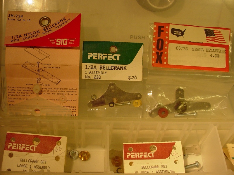
Thanks Rusty and Ken for the advice. My bell-crank/lead-out arrangements will benefit. Rusty, I have a small Sig nylon unit.. and also some other choices in metal.
I like Ken's suggestion for using buttons to attach the lead-outs, I just didn't know how easy it was to make them yourself. I can save both of my little self-designed bell-cranks if I install buttons in them. I have a pkg. of 3-48 blind-nuts I can use.
Ken, the plywood crank platform will have a deep slot cut for it.. and balsa filler-blocks epoxied-in over it and flush with the top surface of the wing. I felt confident that this would be strong enough. To re-cap.. I wanted to keep the look of the full-size model and didn't want the control system exposed. It would have been easier to accomplish this with a built-up wing.. but that has it's own set of challenges. My engine mounting/firewall is a piece of 1/4" plywood to be imbedded into the leading-edge and boxed each side with 1/16" balsa faired-into the leading-edge. Perhaps I could drill two holes in the firewall for 3/16" hardwood dowels 1 to 1-1/2" long and pin them back into the wing for more support and rigidity? I hadn't thought about the vibration effect on the engine, but it makes sense.. where there's no fuse/cheek-blocks. Dowels may act like a shock-absorbing bumper on impact too.. rather than the firewall alone shearing-off at the backside. This is another reason why I wanted to set the engine back in the wing a little. Leading-edge to front of drive-plate distance is 1.25".
It looks like you guys have changed my mind about using the solids. I have some options for braid.. One being .015" 7-strand stainless.. and the other; Synthetic Spiderwire EZ-Braid .3mm (.011") 30# test line. Would crimp-tubes be okay to use with the synthetic? Ken.. the single-hole adjustable guide for both lead-outs I am really sold on.
Well... I've got lot's more to consider now.. but that's a good thing. Thanks again.. and I certainly welcome more suggestions as I proceed.

I like Ken's suggestion for using buttons to attach the lead-outs, I just didn't know how easy it was to make them yourself. I can save both of my little self-designed bell-cranks if I install buttons in them. I have a pkg. of 3-48 blind-nuts I can use.

Ken, the plywood crank platform will have a deep slot cut for it.. and balsa filler-blocks epoxied-in over it and flush with the top surface of the wing. I felt confident that this would be strong enough. To re-cap.. I wanted to keep the look of the full-size model and didn't want the control system exposed. It would have been easier to accomplish this with a built-up wing.. but that has it's own set of challenges. My engine mounting/firewall is a piece of 1/4" plywood to be imbedded into the leading-edge and boxed each side with 1/16" balsa faired-into the leading-edge. Perhaps I could drill two holes in the firewall for 3/16" hardwood dowels 1 to 1-1/2" long and pin them back into the wing for more support and rigidity? I hadn't thought about the vibration effect on the engine, but it makes sense.. where there's no fuse/cheek-blocks. Dowels may act like a shock-absorbing bumper on impact too.. rather than the firewall alone shearing-off at the backside. This is another reason why I wanted to set the engine back in the wing a little. Leading-edge to front of drive-plate distance is 1.25".
It looks like you guys have changed my mind about using the solids. I have some options for braid.. One being .015" 7-strand stainless.. and the other; Synthetic Spiderwire EZ-Braid .3mm (.011") 30# test line. Would crimp-tubes be okay to use with the synthetic? Ken.. the single-hole adjustable guide for both lead-outs I am really sold on.
Well... I've got lot's more to consider now.. but that's a good thing. Thanks again.. and I certainly welcome more suggestions as I proceed.
 Re: "Phred's Phault"
Roddie, I wouldn't use crimp tubes on synthetic lines. You create a hard point in the lines doing so and there's no way of telling if you've sufficiently crimped the lines without damaging it. If you tie the proper knot, it's not going to fail. Don't glue the knot either. It won't slip or fail. If it fails, you didn't tie it correctly. Phil Cartier has a very detailed 8x11 Xerox copy of the knot he uses in step by step. I might be able to get a clear picture of this for you. It's so easy it's ridiculous. Phil has been using the same set of lines for combat for 6 years now. The yellow color has faded and is completely white. We pull test prior to every flight.
My nose blocks recess back into the foam, I run a 1/4" hardwood dowel perpendicular to my nose block which is 4" long in my 1/2A's. I split my wings in half due to using a carbon arrow shaft in the middle. I make this fit very accurately and the dowel holes in each root of the wing receives Pro Bond or Gorilla glue. Ken
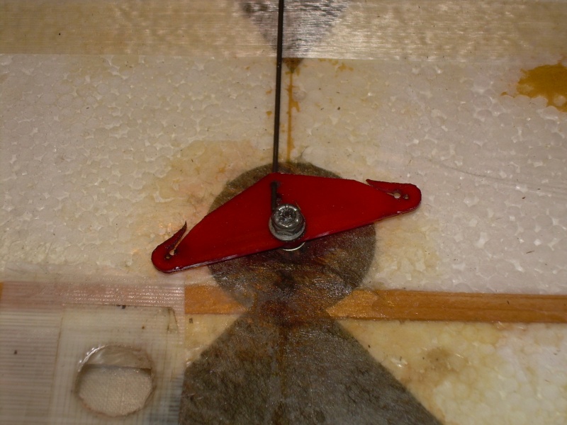
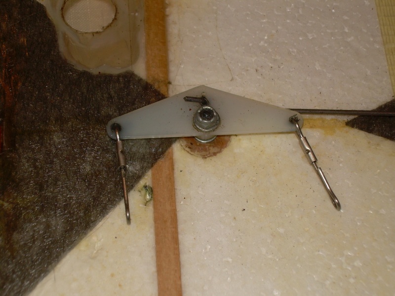
I would also like to add some pics of my Litehawk's I'm currently flying with Sig bellcranks. This also does away with leadouts. Leadouts are problematic as mentioned. In addition, I can cut all of my line lengths to one size regardless of plane. While this is of no concern to those that don't fly competitively, the correct line length for flying 1/2A combat is 42' + or - 3"center to center. Cox engines however are less powerful and still use 35' line lengths. The rules got changed some time back and while the Cox engines can fly on 42' they're not doing it without a struggle. If you have different planes like I do, this requires several different line lengths. having your lines attaching directly to your bellcrank keeps everything the same. Here's how I utilize Sig bellcranks. I use medium clips for 15's on the crank or I redrill new holes and saw down to them. I also use allen socket heads due to steel screws bending and or snapping during flight which has happened to me more than once.


Ken Cook- Top Poster

- Posts : 5640
Join date : 2012-03-27
Location : pennsylvania
 Re: "Phred's Phault"
Thanks Ken, so Gorilla glue (polyurethane base) is foam-safe? I think I read that somewhere.. Could I use this throughout as my adhesive of choice? I think I have some.. I'll have to check.. seems I read that dampening the surfaces to be glued with water, was recommended?
I'd split the wing and incorporate a chord-wise piece of basswood or ply.. but I'd have to redesign my firewall to key into it. It would add a lot of strength though.. and as you pointed out.. do a better job at dampening vibration.
As far as knotting synthetic line goes.. I had my first experience tying the 5-turn uni-knot last Spring when I made-up the 42' line-set for my Rare Bear CEF Reed Speed model. I assume that this knot would be sufficient if I go that route?
 Re: "Phred's Phault"
Here's an attempt at buttons.
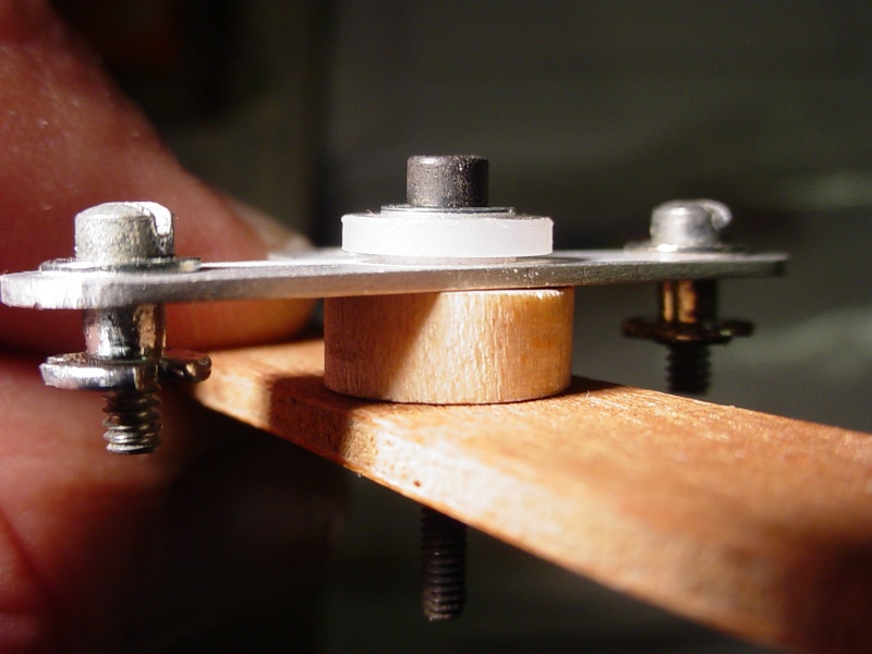
Note the switch to a hex-head pivot screw.. (also Ken's advice) Although the buttons are on the bottom.. I don't think this should matter. I oriented them that way for less of a stress-angle at the pivot. One thing I've never seen (which isn't saying much..) is a dual lower-upper bell-crank platform the width of a rib bay.. and keyed into the spar(s). It would be like a "box". The pull-force would be centralized.. and bushing-wear would be minimized. Has anyone seen this kind of construction on a bell-crank mount?
Okay... I'm an idiot. Rusty's wing clearly shows this.. (hey ... I was concentrating on the lead-outs...)
 Re: "Phred's Phault"
Roddie, you certainly put that together quick. Wow, I'm impressed. As for your buttons being upside down, I think they will prove most problematic in trying to get your loops onto it. I see little stress being applied and that allen head isn't going to let loose. Your flying a Cox powered model not a .60 size stunter. One thing you can do with your newly designed bellcrank is to cut off the excess length of thread hanging out of the blind nut and solder the top of them. They will never come out. Just make sure your blind nuts are burr free in the event you choose to use Spectra Pro Braid or Spiderwire. This is imperative. Using steel lines you don't really have to worry as much. Gorilla glue doesn't eat foam either. It's totally compatible. My suggestion however is to not wet the foam prior to gluing. When you wet Gorilla glue it quadruples itself. For instance, if I have a broken wing that's in need of repair and some of the foam is missing, I can wet that area and load that with a bit more glue and place a piece of packing tape over the void. It will grow into that void and only slightly raise above the surface. It doesn't sand so don't waste your time trying. Ken

Ken Cook- Top Poster

- Posts : 5640
Join date : 2012-03-27
Location : pennsylvania
 Re: "Phred's Phault"
Ken Cook wrote:Roddie, you certainly put that together quick. Wow, I'm impressed. As for your buttons being upside down, I think they will prove most problematic in trying to get your loops onto it. I see little stress being applied and that allen head isn't going to let loose. Your flying a Cox powered model not a .60 size stunter. One thing you can do with your newly designed bellcrank is to cut off the excess length of thread hanging out of the blind nut and solder the top of them. They will never come out. Just make sure your blind nuts are burr free in the event you choose to use Spectra Pro Braid or Spiderwire. This is imperative. Using steel lines you don't really have to worry as much. Gorilla glue doesn't eat foam either. It's totally compatible. My suggestion however is to not wet the foam prior to gluing. When you wet Gorilla glue it quadruples itself. For instance, if I have a broken wing that's in need of repair and some of the foam is missing, I can wet that area and load that with a bit more glue and place a piece of packing tape over the void. It will grow into that void and only slightly raise above the surface. It doesn't sand so don't waste your time trying. Ken
Yes.. it seems that most decent glues for foam don't sand.. I'll put together some .015 stainless braid lead-outs.. and see if I like them. If so, they will be installed on the buttons before I glue-in the assembled bellcrank/platform.. so they'll already be attached. I'm thinking of hand routing deeper slots (DremelTool/router base.. thanks Dad!) into the wing.. so that I'll have a level shot out the tip.. and a more centered roll axis. It's only 6" of foam-span from the bellcrank bay to where the balsa tip attaches. I could cap-over the slot (box-it) with 1/16" balsa, flush with the top of the wing. A little work.. but I think it would be worth it. It would also establish a mount for a simple adjustable guide inside the tip.
 Re: "Phred's Phault"
I had a band gig last night.. and spent a good part of today cleaning my music room (previously occupied by my wife's son...) so I can work toward trying music as a business again.. More on that later.
I mentioned my dad giving me his dremel-tool router attachment. I had not opened the box until today, and it looks to be very well designed. It states that it comes with a straight-bit.. so when checking for it, I found that the parts-bag was un-opened. He'd never used it.
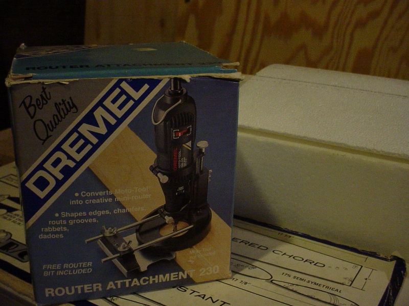
I'm going to cut my lead-out channel(s) with it. This will allow consistent cutting at a pre-set depth, which is my main concern. I have concerns with cutting a fairly deep and wide channel down the top of the wing. Breaking through at the tip primarily.. so it gave me an idea. When I continue on my balsa tip-extensions, the inboard will be built on a 1/32" ply "tip-rib".. and give me some options for a guide set-up. Bridging the channel-gap with a thin-ply tip-rib will restore some rigidity.. with little weight.. probably less weight than the foam to be removed.
For an adjustable guide.. I once made a 2-piece "comb?" type unit for solids.. Teeth allowed for either lead-out to be moved fore/aft.. pick a position, lay them in and close the latch. For these braided lines, I think I'll slot the tip-rib horizontally.. enough for the lead-outs and their terminations to pass through, and leave it that way until I finish the model. At that point I can hang the wing, mark a location.. and close-off the slot on either side. This tip-rib is gonna' take some thought.. because the slot is going to take some abuse. I could use pieces of .015" music-wire CA glued above and below the slot.. to keep the stainless braid from wearing on the plywood. When I set the guide location and close up the slot (at finish) I'll have to come up with something to deal with the lateral forces as well. Maybe a small "closed" safety pin, epoxied vertically across the slot? Easy to install.. and the lines ride inside.
Ken mentioned running both lead-outs through one guide. This would accomplish that.
I mentioned my dad giving me his dremel-tool router attachment. I had not opened the box until today, and it looks to be very well designed. It states that it comes with a straight-bit.. so when checking for it, I found that the parts-bag was un-opened. He'd never used it.

I'm going to cut my lead-out channel(s) with it. This will allow consistent cutting at a pre-set depth, which is my main concern. I have concerns with cutting a fairly deep and wide channel down the top of the wing. Breaking through at the tip primarily.. so it gave me an idea. When I continue on my balsa tip-extensions, the inboard will be built on a 1/32" ply "tip-rib".. and give me some options for a guide set-up. Bridging the channel-gap with a thin-ply tip-rib will restore some rigidity.. with little weight.. probably less weight than the foam to be removed.
For an adjustable guide.. I once made a 2-piece "comb?" type unit for solids.. Teeth allowed for either lead-out to be moved fore/aft.. pick a position, lay them in and close the latch. For these braided lines, I think I'll slot the tip-rib horizontally.. enough for the lead-outs and their terminations to pass through, and leave it that way until I finish the model. At that point I can hang the wing, mark a location.. and close-off the slot on either side. This tip-rib is gonna' take some thought..
Ken mentioned running both lead-outs through one guide. This would accomplish that.
 Re: "Phred's Phault"
roddie wrote:Be sure to let us know, if you decide on a build. Good luck!
Will do

Thanks for the numbers, I'll check the measurements of the cores when I go to the store next time.
I have no experience on foam cutting or making planes out of plastic. I have used the same cores as above for a couple of free flight gliders before but that was 30+ years ago. So far I have built rest of my planes using balsa, pine, birch plywood and other "old school" stuff.
I get dizzy easily, so for the first plane I would like something slow, that's why I was looking at something with a relatively thick wing profile, and something that actually flies "aerodynamically" unlike a slab wing plane. Maybe I'm just overthinking it and maybe the C/L world is a little bit different
The foam cores with a slab fuselage would be a rather quick and inexpensive experiment, sanding them down a bit from the bottom sides was a good point, thanks. If I end up building one and the Babe Bee is underpowered, I may try a QRC, that should give more power, especially unmuffled. Then there's the Medallion too, but as I have 3 or 4 Babe Bees, I think they are the most "disposable" for basic training use.

KariFS- Diamond Member

- Posts : 2044
Join date : 2014-10-10
Age : 53
 Re: "Phred's Phault"
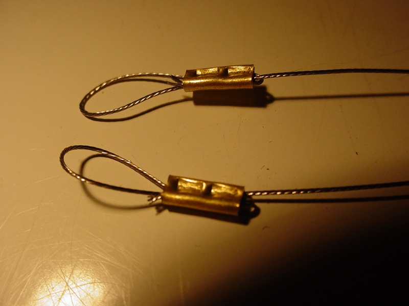
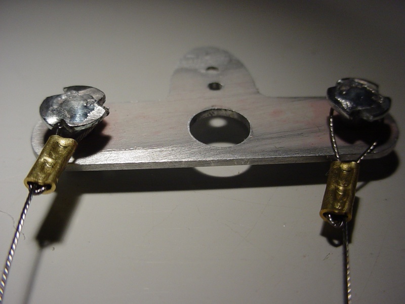
A little more work on my control system. These are .015" stainless braid lead-outs with loops formed for the bellcrank buttons I made.
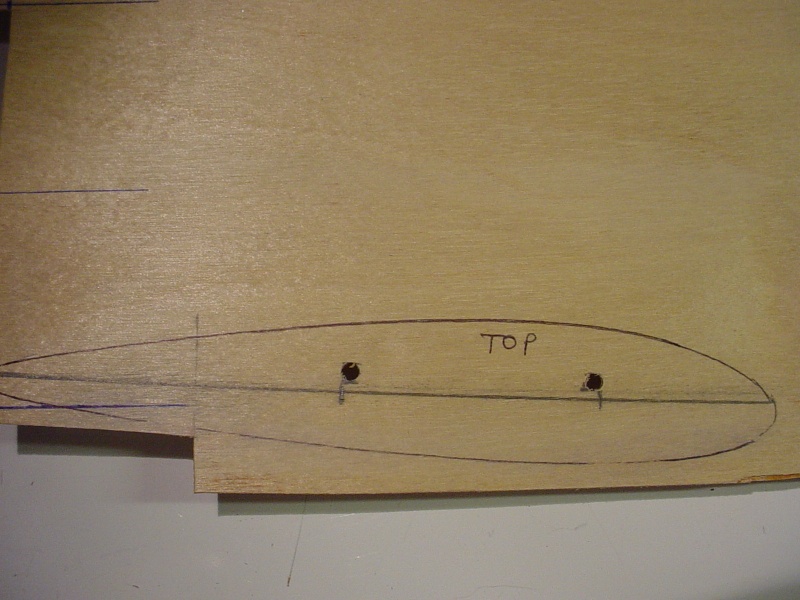
I mentioned making an adjustable guide by using a 1/32" plywood inboard tip rib. I made one, and also a 1/16" balsa outboard tip-rib. These will be epoxied to the foam after they're built-up.. and the wing will finish-out at 18-3/8" span.
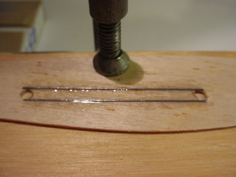
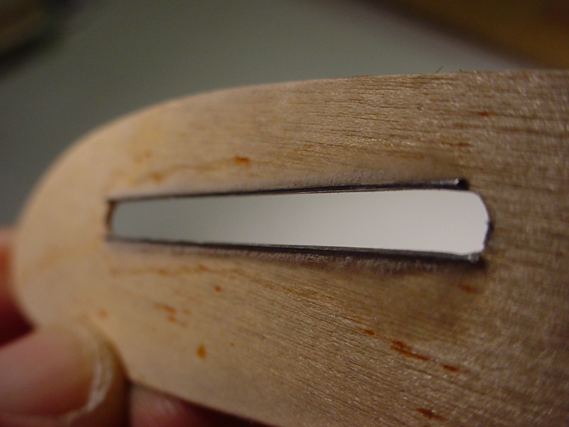
I framed the lead-out slot to be cut, with .015" music-wire, CA glued in place; top and bottom.. to prevent the stainless braid from wearing on the plywood rib. This also made it easier to cut a straight slot.
Both.. balsa( top) and ply (bottom) tip-ribs cut.
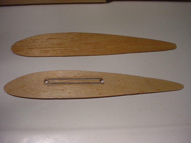
My lead-out slot cut-out done.
Here are my finished bellcrank buttons with lead-outs installed. I'm concerned that the loops are a little big.. Maybe if I pinch the loops closed slightly.. I wouldn't have to worry about them coming off the buttons?
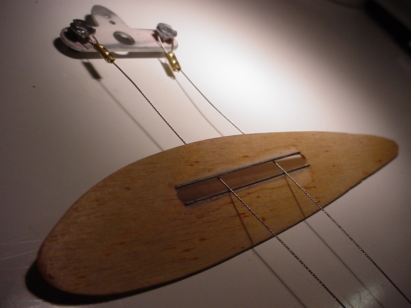
The bellcrank is actually shown upside down here.. but this is how I plan to run my lead-outs inside the foam and out through the tip.
At finish.. the preliminary lead-out position will be set by anchoring this safety-pin vertically to the rib, for both lines to run through. I think that small "round-head" common-pins; top and bottom.. through the holes in the safety-pin will hold securely with a drop of thin CA on the shaft. That way I can remove them if I need to move the lead-out's for a different balance-point.
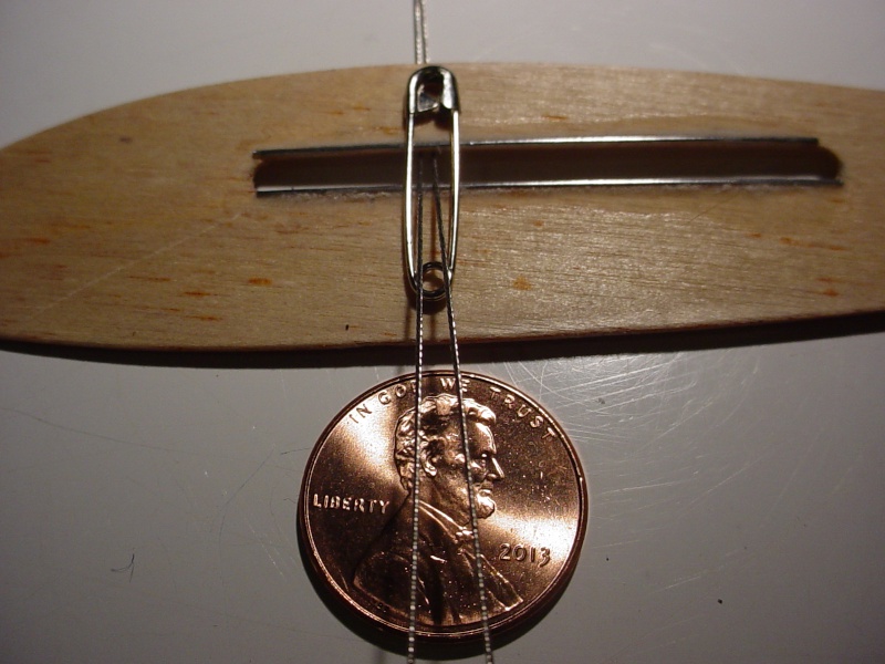

I mentioned making an adjustable guide by using a 1/32" plywood inboard tip rib. I made one, and also a 1/16" balsa outboard tip-rib. These will be epoxied to the foam after they're built-up.. and the wing will finish-out at 18-3/8" span.

I framed the lead-out slot to be cut, with .015" music-wire, CA glued in place; top and bottom.. to prevent the stainless braid from wearing on the plywood rib. This also made it easier to cut a straight slot.

Both.. balsa( top) and ply (bottom) tip-ribs cut.

My lead-out slot cut-out done.

Here are my finished bellcrank buttons with lead-outs installed. I'm concerned that the loops are a little big..
 Maybe if I pinch the loops closed slightly.. I wouldn't have to worry about them coming off the buttons?
The bellcrank is actually shown upside down here.. but this is how I plan to run my lead-outs inside the foam and out through the tip.

At finish.. the preliminary lead-out position will be set by anchoring this safety-pin vertically to the rib, for both lines to run through. I think that small "round-head" common-pins; top and bottom.. through the holes in the safety-pin will hold securely with a drop of thin CA on the shaft. That way I can remove them if I need to move the lead-out's for a different balance-point.

 Re: "Phred's Phault"
As our circle marshal explicitly yells out "COMBAT!!!" This should be flying prior to Thanksgiving dinner. Ken

Ken Cook- Top Poster

- Posts : 5640
Join date : 2012-03-27
Location : pennsylvania
 Re: "Phred's Phault"
Ken Cook wrote: As our circle marshal explicitly yells out "COMBAT!!!" This should be flying prior to Thanksgiving dinner. Ken
Hey Ken, That would be nice.. but it ain't gonna' happen..
 Does the "gap" in the guide look ok to you? It's about 1/8" square using the safety-pin as a lateral set-point. Is this too much "slop" on a model this small?
I plan on making the line-connector ends off-set in length.. about 3/4" to 1" to prevent them from snagging on each other. The control-throws will be set very short to start with.. (pushrod on the inner-hole on the crank.. and outer-most hole on the horn).
I drilled my firewall for running two pieces of 3/16" hardwood dowel, to pin back into the foam. One is shorter because it comes close the bellcrank plate.

The 290 mounts that I made, have a fairly wide spread. The hole pattern measures 1-1/16" x 17/32". I'd like to think that this might help to spread-out engine vibration a little better.. although I did not design them for that purpose. The 17/32" spacing is the same as the engine's case-screw spacing.. which I transferred to the firewall mount for simplicity. The 1-1/16" spacing was the narrowest I could achieve.. and still have room for mounting screws/washers to the firewall. This works out well from a streamlining standpoint, with the mount oriented horizontally.. but places the NVA vertically because the mounts will only fit between the molded-plastic ears on the back of a 290 style backplate.
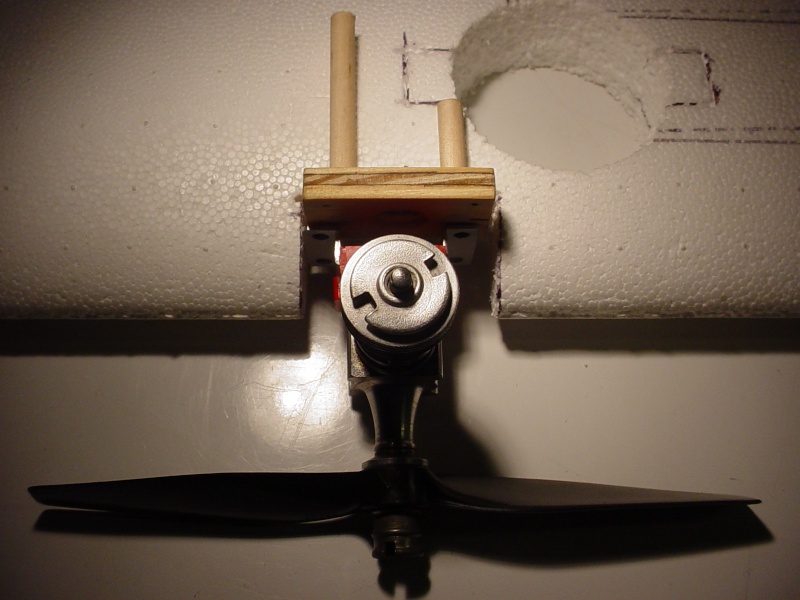
 Re: "Phred's Phault"
My biggest concern would be a ground strike. I can see bad things happening with the way that firewall attaches. It looks like the entire assembly would just break out of the foam. Glassing the nose with some lightweight cloth and thinned white glue all around the firewall and back onto the wing would help. Even if you stuffed it, and the engine didn't break off, it could push back into the wing and certainly into your bellcrank area. I see a stress riser created from the corner of the firewall notch into the circular bellcrank cutout. Were going to keep our fingers crossed here and your not going to hit the ground. Keep saying that over and over. Ken

Ken Cook- Top Poster

- Posts : 5640
Join date : 2012-03-27
Location : pennsylvania
 Re: "Phred's Phault"
Ken Cook wrote:My biggest concern would be a ground strike. I can see bad things happening with the way that firewall attaches. It looks like the entire assembly would just break out of the foam. Glassing the nose with some lightweight cloth and thinned white glue all around the firewall and back onto the wing would help. Even if you stuffed it, and the engine didn't break off, it could push back into the wing and certainly into your bellcrank area. I see a stress riser created from the corner of the firewall notch into the circular bellcrank cutout. Were going to keep our fingers crossed here and your not going to hit the ground. Keep saying that over and over. Ken
Thanks Ken, I'll see if I can work something out.. hopefully without adding too much weight.
 Re: "Phred's Phault"
An additional solution may be 3/32" or 1/8" ply cheek pieces that glue on the sides of the engine mount bulkhead going forward to wing leading edge, which in turn are glued to the edges of the foam wing from bulkhead to wing leading edge. This would increase the glue area with the foam plus support the engine from minor ground strikes by reducing vertical shear moment (freedom to turn) on the bulkhead. Epoxy glue cloth or glass hinge tape along the edges of the foam and ply/bulkhead joint area to strengthen it.

GallopingGhostler- Top Poster


Posts : 5724
Join date : 2013-07-13
Age : 70
Location : Clovis NM or NFL KC Chiefs
 Re: "Phred's Phault"
Or you could make a closed "box" as on the Lil Satan
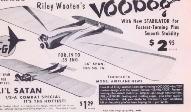
and fix a piano wire skid to facilitate landings and prevent prop damage. Below 2 examples used on combat planes
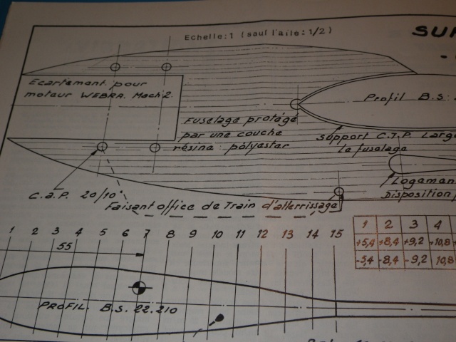


and fix a piano wire skid to facilitate landings and prevent prop damage. Below 2 examples used on combat planes


OVERLORD- Diamond Member

- Posts : 1807
Join date : 2013-03-19
Age : 58
Location : Normandy, France
 Re: "Phred's Phault"
I see it now, your engine mount is, I think, not higher than the thickness of the wing at the cut out. No box then!!

OVERLORD- Diamond Member

- Posts : 1807
Join date : 2013-03-19
Age : 58
Location : Normandy, France
 Re: "Phred's Phault"
Roddie , I know Ken knows what he is talking about , but I personally don't like the idea of the lead outs having no constrictions from each other  I don't see control with them going from side to side in a slot ? The mount I would glass in behind that mount and the sides I don't think I would worry to much about that added weight over strength value
  I have never worked with foam and don't think I want to at this point just my
  Getback
 I have never worked with foam and don't think I want to at this point just my
  Getback
getback- Top Poster


Posts : 10442
Join date : 2013-01-18
Age : 67
Location : julian , NC
 Re: "Phred's Phault"
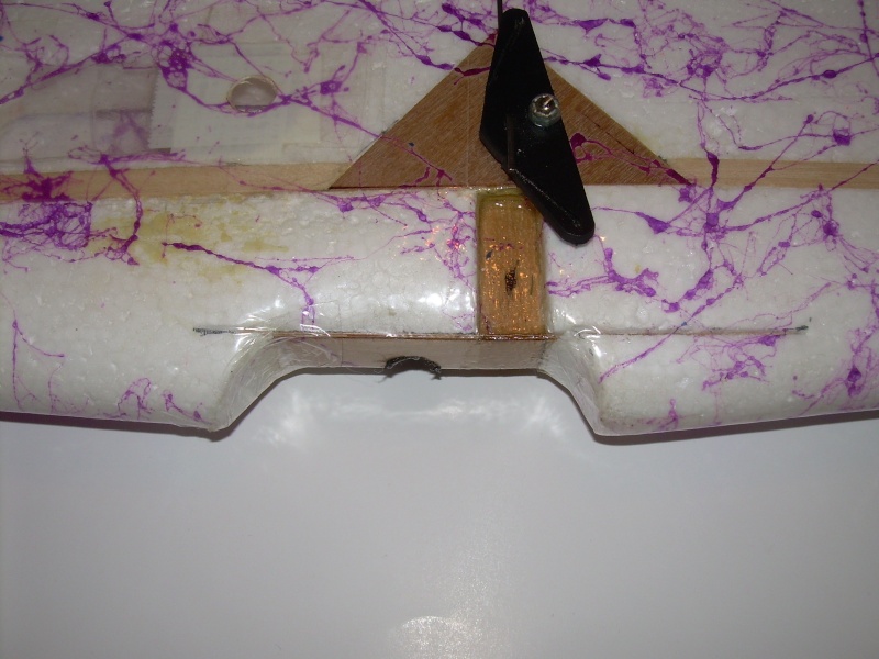
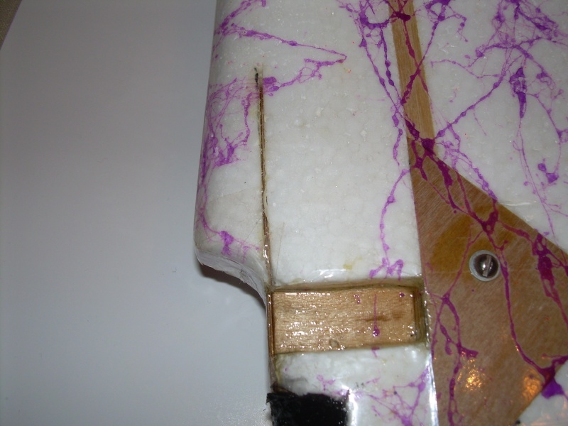
Roddie, I would go ahead with your mount but I would cut a slot for a 1/32" ply biscuit which would span across the firewall going a few inches on each side of the wing root. Here's a pic of one of mine and also the way the ply spans across. Don't use epoxy with fiberglass. It will add too much weight. Using thinned glue is easier and cleaner to work with and it's very strong. Once the biscuit is going across the entire assembly is when you should incorporate the glass over everything. The entire front of this engine area is glassed to the back of the spar. Ken


Ken Cook- Top Poster

- Posts : 5640
Join date : 2012-03-27
Location : pennsylvania
 Re: "Phred's Phault"
 I've been writing/thinking for the last two hours.. (see below RE;Lieven) Thanks guys! I've got some options.. but some I'm going to have to learn how to do.. if I try them. Ken, you mentioned thinned glue.. What type and thinner?
OVERLORD wrote:I see it now, your engine mount is, I think, not higher than the thickness of the wing at the cut out. No box then!!
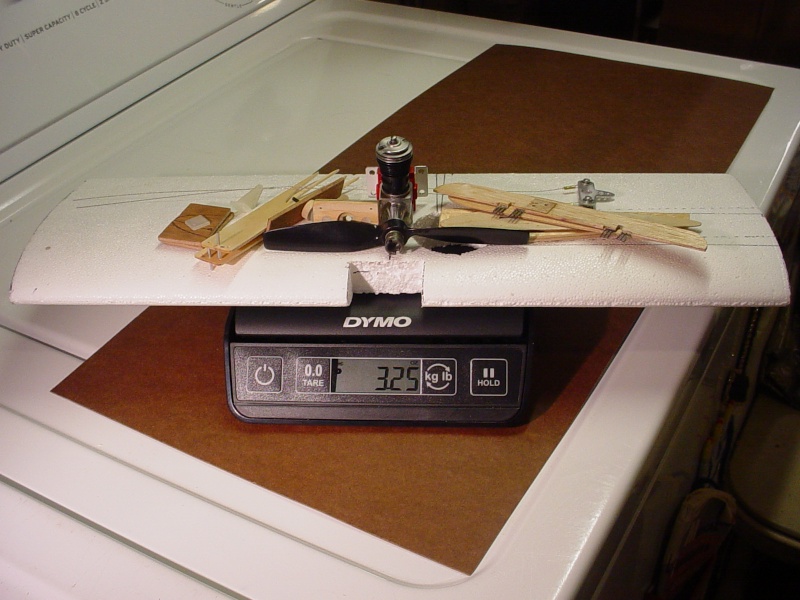
Correct Lieven. George's idea is one that I had already planned on.. but for a different reason. Since the firewall is set back.. the notch cut in the leading-edge leaves foam edges that would get rounded/chipped-off. I had planned to fill this area with 1/16" hard-balsa. Even if I opted for plywood.. I can't really "key-into" the firewall with them, for the rigidity that Ken's concerned about. I have the two forces of "squish" on a direct nose-in.. and "shear' with a more angular ground-strike, that are going to be problems with my mount, the way it is now. The hole for the bellcrank is a big issue here. It's too close to the firewall cut-out. The best single thing I can do, is to tie the firewall into the plywood bellcrank platform somehow. I have the Dremel-tool w/router kit for slotting.. maybe I could notch the firewall, slot the wing chordwise behind the firewall a few inches and lay-in some 1/8" sq. Spruce top and bottom? Whatever I do.. it's gotta' be lightweight. I'm already at 3-1/4 ounces.. less a pushrod, glue-up and covering.
 Re: "Phred's Phault"
getback wrote:Roddie , I know Ken knows what he is talking about , but I personally don't like the idea of the lead outs having no constrictions from each otherI don't see control with them going from side to side in a slot ? The mount I would glass in behind that mount and the sides I don't think I would worry to much about that added weight over strength value
I have never worked with foam and don't think I want to at this point just my
Getback
Eric, the lateral slot for my lead-outs is only for fore-aft adjustment. Once balanced (at finish) their lateral location is pinned-in. I show a small safety-pin to be secured to the rib vertically for this.. but may do something different. Whatever it is.. the lead-out position will certainly be fixed.. and not sliding.
 Re: "Phred's Phault"
Ken Cook wrote: As our circle marshal explicitly yells out "COMBAT!!!" This should be flying prior to Thanksgiving dinner. Ken
2nd time I've quoted Ken.. Not much to report...
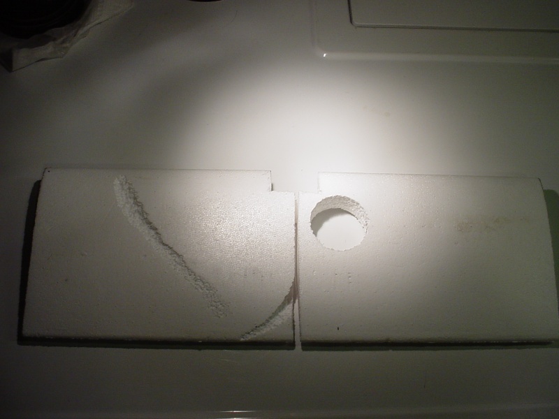
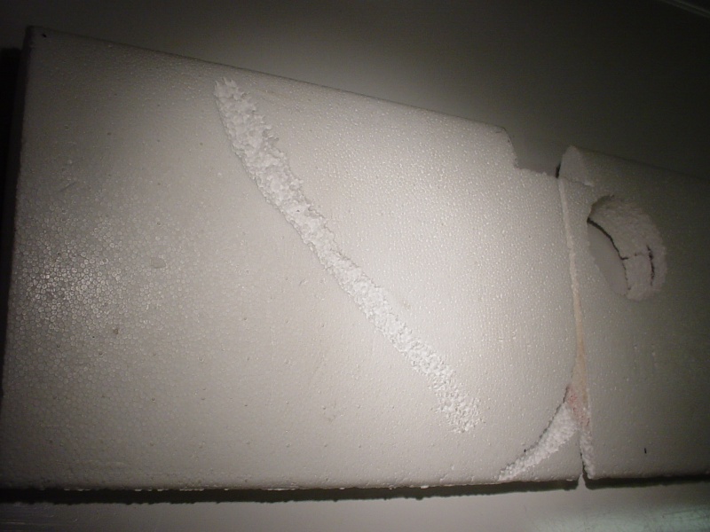
Econokote will cover this.. but it was a dumb mistake. I was planning on installing a central ply-rib that would key into my radial "290" engine mounting.. but I thought about the option of building a "box" that would tie-in the engine-mount/firewall, bellcrank-platform and the tail-booms. The foam core "panels" would then become "extensions" off the fuse.. instead of being an integral part of the airframe. I'll admit that it's an unorthodox construction for a wing.
 but it could also provide for a centralized bladder-bay. Some considerations... a "box" would have to be the width of the booms.. and ideally; the booms would extend forward to the firewall. The boom-spacing on this model is 2-3/8" on center. If I make inside cheek-blocks of balsa for the engine-mount.. they might provide a (edit) "crumple-zone" in the event of a "nose-in".
 I may re-build my tail-booms.. and go "full-chord" with some 3mm plywood that I have an abundance of. I can't really afford to buy 1/16" aircraft birch right now. This wood I got several years ago.. and it was actually used as packing material.. like part of a "crate". Well.. I saved it.. because it's useful where you need a little more strength.
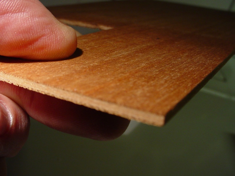
I have 3 or 4 full-sheets 12" x 24".. as well as several remnant sheets. It's "overkill" for this 1/2A VooDoo.. but I have a sheet in queue for the boom-stock for the "full-size" VooDoo build.. that Lieven sent me templates for. (Thanks Lieven!... to you; I have a full-template set.. and an illustrated "improvements" article.) That will be a much more "straight-forward" build than this one. Wing-tips, booms/tail-plane, bellcrank/engine mount.. and a good tank set-up.. and that should be good to go.. seeing that the wing is mostly built.
 Re: "Phred's Phault"
I'd simply splice some expanded polystyrene foam from say an electronics shipping sales box. Use white or carpenters water based glue, put some weight or bands to hold until it dries. Hit it with a hand block sander and coarse paper until contoured, then finer grades to finish. After Econokoting or other favorite low temperature film, should be ready to go.
This is how I repair foam wings after crashes or severe hangar rash.
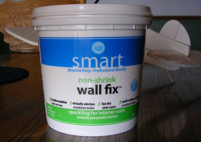
Additional note, if the marring is shallow I've used synthetic spackling to fill imperfections.
This is how I repair foam wings after crashes or severe hangar rash.

Additional note, if the marring is shallow I've used synthetic spackling to fill imperfections.

Last edited by GallopingGhostler on Mon Dec 22, 2014 6:28 am; edited 1 time in total (Reason for editing : Added additional comment.)

GallopingGhostler- Top Poster


Posts : 5724
Join date : 2013-07-13
Age : 70
Location : Clovis NM or NFL KC Chiefs
 Re: "Phred's Phault"
 MAN , I was wondering how that foamy was coming along , I know it is the busy time of the year for most people // I still got two wreaks I need to glue back together and some covering to do before I start ANYTHING else
  Eric
Eric
getback- Top Poster


Posts : 10442
Join date : 2013-01-18
Age : 67
Location : julian , NC
 Re: "Phred's Phault"
getback wrote:MAN , I was wondering how that foamy was coming along , I know it is the busy time of the year for most people // I still got two wreaks I need to glue back together and some covering to do before I start ANYTHING else
Eric
I wish I could say I was more busy Eric... I hadn't touched this little foamie for weeks before attempting to cut that wing in half the other day. The table-saw was the only tool I had to make a perpendicularly square cut.
Thinking more on this... a single-central 3mm ply-rib should provide strength for two critical areas of this design; the firewall rearward.. and the bellcrank mount-plate which I could glue into a slot cut in the rib.
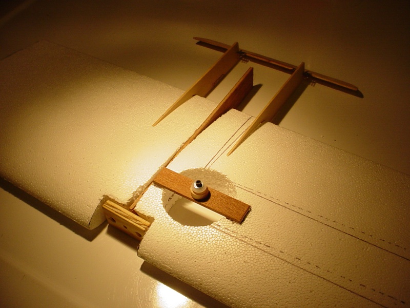
I had drilled the firewall for 1/4" dowels to pin-back into the foam.. If I only install the outboard (longer) one, it will lessen the chance of the firewall shearing into that open bellcrank-bay on the inboard panel. George's recommendation for boxing the firewall "forward".. and fairing into the leading-edge, will provide some more strength too.. as well as protecting the foam from dings in that area.
Page 3 of 7 •  1, 2, 3, 4, 5, 6, 7
Page 3 of 7
Permissions in this forum:
You cannot reply to topics in this forum

 Rules
Rules

