Log in
Search
Latest topics
» Purchased the last of any bult engines from Ken Enyaby sosam117 Today at 12:32 pm
» Chocolate chip cookie dough.........
by rsv1cox Today at 11:20 am
» Tee Dee .020 combat model
by rsv1cox Today at 11:07 am
» Free Flight Radio Assist
by rdw777 Today at 10:24 am
» My latest doodle...
by batjac Yesterday at 10:47 pm
» My N-1R build log
by roddie Yesterday at 9:50 pm
» Funny what you find when you go looking
by rsv1cox Wed Nov 20, 2024 4:21 pm
» Landing-gear tips
by 1975 control line guy Wed Nov 20, 2024 9:17 am
» Cox NaBOO - Just in time for Halloween
by rsv1cox Tue Nov 19, 2024 7:35 pm
» Canada Post strike - We are still shipping :)
by Cox International Tue Nov 19, 2024 1:01 pm
» Duende V model from RC Model magazine 1983.
by getback Tue Nov 19, 2024 7:08 am
» My current avatar photo
by roddie Mon Nov 18, 2024 10:05 pm
Cox Engine of The Month
CEF speed contest Design Discussions
Page 10 of 40
Page 10 of 40 •  1 ... 6 ... 9, 10, 11 ... 25 ... 40
 Re: CEF speed contest Design Discussions
On a previous plane it is holding up pretty good as a base coat. I don't have any coating failure so far. I did feel the plane became very heavy with paint as I didn't remove much of each coat via sanding or some other method.
On this one I used denatured alcohol on a scrub pad to smooth the surface, which worked very quickly. I haven't gotten color onto the plane yet though. The polycryllic is completely coated with grey rustoleum primer (sanded down) and white rustoleum paint. I just need to mask and do color trim.
Phil

pkrankow- Top Poster

- Posts : 3025
Join date : 2012-10-02
Location : Ohio
 Re: CEF speed contest Design Discussions
I have a couple of questions.
I've never used a sealer, Polycryllic or other, and don't really know what the purpose is.
Does the Polycryllic and sanding treatment fill in all of the balsa grain, or is the primer needed for that?
Why do you coat it with white, rather than just applying the color?
Thanks for any finishing tutelage y'all can give me.
The previously improperly finished Rusty
_________________
Don't Panic!
...and never Ever think about how good you are at something...
while you're doing it!
My Hot Rock & Blues Playlist
...and never Ever think about how good you are at something...
while you're doing it!
My Hot Rock & Blues Playlist

RknRusty- Rest In Peace

- Posts : 10869
Join date : 2011-08-10
Age : 68
Location : South Carolina, USA
 Re: CEF speed contest Design Discussions
White is the base color, orange and black are the trim colors. The model will be over 50% white when I am done.
A base color of white also can be used under lighter colors to make the finish color uniform and bright (although this is added weight, especially with rustoleum).
Sanding sealer is to stabilize the wood so the fibers cut with sandpaper easily instead of burnishing. It also helps fill the grain. Instead of sanding I cleaned off the extra sealer with a chemical (denatured alcohol) which left the sealer in the grain. I probably should have recoated and scrubbed it again as there was some grain left showing. It could be said I was burnishing the grain closed with the scrub pad.
The primer is also to fill grain. The process of priming and sanding also shows minor blemishes so they can be dealt with.
With a higher finish desired that this plane is getting I would use dissimilar color primers starting with one color, then adding a couple layers of the other color , then sanding until at least 50% of the first color is visible. I have done this on a car after doing bodywork, but not on a model. I did get very good results on that car though.
I am aiming for a step above my usual finish on this model, but I am not striving for perfection.
Phil

pkrankow- Top Poster

- Posts : 3025
Join date : 2012-10-02
Location : Ohio
 Re: CEF speed contest Design Discussions
Thanks Phil. I won't go for perfection either, but I do want to step up my finishing quality, and this is a good opportunity to start.
Rusty
Rusty
_________________
Don't Panic!
...and never Ever think about how good you are at something...
while you're doing it!
My Hot Rock & Blues Playlist
...and never Ever think about how good you are at something...
while you're doing it!
My Hot Rock & Blues Playlist

RknRusty- Rest In Peace

- Posts : 10869
Join date : 2011-08-10
Age : 68
Location : South Carolina, USA
 Re: CEF speed contest Design Discussions
Phil
I'll be going with my standard white and orange also.
I'll be going with my standard white and orange also.

duke.johnson- Diamond Member

- Posts : 1734
Join date : 2012-11-05
Age : 53
Location : Rochester, Washington
 Re: CEF speed contest Design Discussions
I'm not changing my design. Sorry. I do look forward to seeing your design all the same.duke.johnson wrote:Phil
I'll be going with my standard white and orange also.
Phil

pkrankow- Top Poster

- Posts : 3025
Join date : 2012-10-02
Location : Ohio
 Re: CEF speed contest Design Discussions
Yes, I'll try that. I don't know what would be the lightest solution, to cover it in Oracover or layers of dope, paint, and varnish?duke.johnson wrote:Looks really fast. Are you going with the same paint scheme?
Lieven

OVERLORD- Diamond Member

- Posts : 1807
Join date : 2013-03-19
Age : 58
Location : Normandy, France
 F8F-2 tank work
Tiny tank... 1.250"L. x .5"W. x .75"H. = .26oz./7.7cc's. My 40w. elec. iron with a 1/4" wide wedge-tip won't flow solder on a test joint. I gotta' go hotter...


I made-up 4 tank assemblies... hopefully I'll get one that seals and works well.


I made-up 4 tank assemblies... hopefully I'll get one that seals and works well.
 Re: CEF speed contest Design Discussions
That starts looking good Roger. Have you tried your butane burner already for soldering the joints?
Lieven
Lieven

OVERLORD- Diamond Member

- Posts : 1807
Join date : 2013-03-19
Age : 58
Location : Normandy, France
 Re: CEF speed contest Design Discussions
Thanks Lieven... no I haven't... but I think I know why I was having trouble. I had a pc. of Copper-tube running through a test-cap/panel... with the tubing held in a vise. I think the steel vise jaws may have been "sinking" all the heat away. I will try the elec. iron again; laying the pieces on a wood block.OVERLORD wrote:That starts looking good Roger. Have you tried your butane burner already for soldering the joints?
Lieven
 Re: CEF speed contest Design Discussions
Ok, It could be that. I don't know if 40W will be enough to solder plates together though. It's all right in electronics to solder wires but here you need to heat up a plate locally to get your joint soldered. But then again, your tank is not that big. Give it another try as you said.
Lieven
Lieven

OVERLORD- Diamond Member

- Posts : 1807
Join date : 2013-03-19
Age : 58
Location : Normandy, France
 Re: CEF speed contest Design Discussions
Yes they're very small tanks of .008" sheet Tin, and I'm concerned about too much heat distorting the panels... I'll just have to be careful if I have to use the micro-torch.
If I can get a couple or "all" of the tanks to the point where it looks like they'll seal well... I might make an interior "windage" panel for one of them... just as an experiment to see if it helps to stabilize the fuel level during a run.
If I can get a couple or "all" of the tanks to the point where it looks like they'll seal well... I might make an interior "windage" panel for one of them... just as an experiment to see if it helps to stabilize the fuel level during a run.
 Re: CEF speed contest Design Discussions
The uniflow vent and pickup openings are awful close to each other. You might want to put a wall between them so as not to pass air from the uni into the feed line.
Pretty work though. I need to learn to do that.
Rusty
Pretty work though. I need to learn to do that.
Rusty
_________________
Don't Panic!
...and never Ever think about how good you are at something...
while you're doing it!
My Hot Rock & Blues Playlist
...and never Ever think about how good you are at something...
while you're doing it!
My Hot Rock & Blues Playlist

RknRusty- Rest In Peace

- Posts : 10869
Join date : 2011-08-10
Age : 68
Location : South Carolina, USA
 Re: CEF speed contest Design Discussions
Hi Roddie,roddie wrote:Tiny tank... 1.250"L. x .5"W. x .75"H. = .26oz./7.7cc's. My 40w. elec. iron with a 1/4" wide wedge-tip won't flow solder on a test joint. I gotta' go hotter...
I made-up 4 tank assemblies... hopefully I'll get one that seals and works well.
This is neat metal work and you are about 5 minutes from a completed tank.
I have made quite a few tanks from brass and tin with copper and brass pipe work.
I have found:-
The larger the tank the easier it is to make.
A pointed soldering bit makes life easier.
Leaded solder is much easier to flow and rework.
You must clean and tin (pre solder) the joints before assembly. I then clamp the together, remelt and add a fillet of solder to the joint.
On a small tank - flanges are not necessary - a fillet is the best way to seal.
I use three irons 30W for tinning, 60W after clamping to make the initial bind and then 15W for applying a fillet. Done slowly, the 15W iron melts the solder locally and not the entire joint. Sorry four irons (I have a gas fired 50W jobby!)
This is and example of a disastrous tank build
https://www.coxengineforum.com/t5641-tank-building?highlight=tank+building
I couldn't get the lead free solder to hold or flow and reorted to the ultimate!
Here is a simpler one made from a tin can - this was the first I had made after many years absence from the hobby.
https://www.coxengineforum.com/t5190-ian-s-cox-flight-contest-progress#66381
Don't adopt my habit of touching things to see if they are hot!

ian1954- Diamond Member

- Posts : 2688
Join date : 2011-11-16
Age : 70
Location : England
 Re: CEF speed contest Design Discussions
Wow, makes my 150W gun look like a howitzer at a pistol range!
A good quality variable temperature soldering station (such as a Weller) is worth the money. It is on my wish list.
I have 4 pencils and a couple other options and the sears 150W/200W gun that can sweat household plumbing (yes, really, but takes forever)
I also agree the uniflow is pretty darn close to the pickup there. These small tanks may not have enough separation possible for uniflow.
Phil

pkrankow- Top Poster

- Posts : 3025
Join date : 2012-10-02
Location : Ohio
 F8F-2 tank work
Yes Rusty... Phil also commented about the tubing positions. I have not even "tacked" anything as of yet. In actuality; the uni-flow tube will be at least 3/16" forward of the feed tube's inlet at the rear of the tank. Ultimate location will be a matter of experimentation, which is why I built x4 tank assy's. The uni-flow tube position will vary slightly w/each tank... but not more than 50% forward of the feed-tube's inlet.RknRusty wrote:The uniflow vent and pickup openings are awful close to each other. You might want to put a wall between them so as not to pass air from the uni into the feed line.
Pretty work though. I need to learn to do that.
Rusty
I mentioned on reply to Lieven; that I may try installing a perforated internal "partition"... not a "wall" as you stated.. but a "sub-floor"; similar to a windage-tray in an oil-pan, to help stabilize the fuel from "sloshing" away or "up" from the pick-up. I think it's a similar principle to a "Chicken-Hopper" tank... but will only need to function in level flight. It will be an "insert".. and not soldered in. Alternating "tabs" will hold it in place inside the tank, with slots cut to clear the internal plumbing. Basically a "baffle".
 F8F-2 tank work
Here's the "slip-in" baffle experiment for one of my 4 tanks. The idea is to stabilize the fuel at the lower/rear/outboard corner of the tank.
It's .005" sheet-brass, with a cut-out to clear the plumbing and bent to fit the width/height/length of the tanks interior.

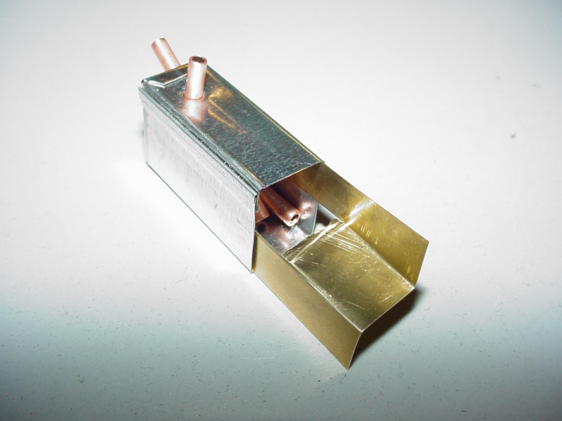

I still haven't soldered anything together yet...
It's .005" sheet-brass, with a cut-out to clear the plumbing and bent to fit the width/height/length of the tanks interior.


I still haven't soldered anything together yet...

 Re: CEF speed contest Design Discussions
I think you are over thinking the baffle, it won't be necessary.
If you are going to use it put a notch on the edge shown too. Half a paper punch hole should do.
Phil
If you are going to use it put a notch on the edge shown too. Half a paper punch hole should do.
Phil

pkrankow- Top Poster

- Posts : 3025
Join date : 2012-10-02
Location : Ohio
 Back for more
Well, my contributions are going to be scarce for a while. Health problems in the family. But I'll make time as I can to build and post. I changed my mind last week about laminating with two 1/16" sheets. I was thinking it might make it tail heavy. So I decided on using 1/32" ply to sandwich the 1/8" balsa. I didn't have a large enough piece in the wood box, so I waited until I went to the other side of town on an errand to stop in at the big hobby shop. The only 1/32" sheet they had was a 24"x48" piece for $28.00, so I passed. Today I made a run to the little local shop. They had exactly one piece of 1/32" ply, at 6"x12". This was perfect for the current job, although I'd have liked to buy a couple more pieces, or a slightly larger piece to have on hand for future projects. When I got home I cut the ply and glued up the sandwich. I also bent up the landing gear.
Cut out for gluing, and laminated together:


Slathering on some balsa filler to the wing joiners to fill the holes:

The fuselage after sanding the sandwich and test fitting the wing and landing gear:


And, this is my first try on a model of something I do when I'm building my full scale plane. I like to take 3D pictures of the plane as I'm building. It looks pretty cool. This picture is pretty good, but the focus of the bent up left wing is a little off. The camera I'm using now doesn't have cross hairs on the viewer, so I have to improvise when taking the pics. To view this picture in 3D, you have to click to enlarge the view and then stare at the line dividing the two pictures with your eyes about 18"-24" away from the screen. Slowly cross your eyes. You'll see the two pictures start to separate and create a third picture in the middle. When the two pictures turn into three full pictures, the center one is in 3D:

The "Clarence" Mark
Cut out for gluing, and laminated together:


Slathering on some balsa filler to the wing joiners to fill the holes:

The fuselage after sanding the sandwich and test fitting the wing and landing gear:


And, this is my first try on a model of something I do when I'm building my full scale plane. I like to take 3D pictures of the plane as I'm building. It looks pretty cool. This picture is pretty good, but the focus of the bent up left wing is a little off. The camera I'm using now doesn't have cross hairs on the viewer, so I have to improvise when taking the pics. To view this picture in 3D, you have to click to enlarge the view and then stare at the line dividing the two pictures with your eyes about 18"-24" away from the screen. Slowly cross your eyes. You'll see the two pictures start to separate and create a third picture in the middle. When the two pictures turn into three full pictures, the center one is in 3D:

The "Clarence" Mark
batjac- Diamond Member


Posts : 2374
Join date : 2013-05-22
Age : 61
Location : Broken Arrow, OK, USA
 Re: CEF speed contest Design Discussions
Roddie I have been watching and tank looking really good ,but I agree with Phil about hole or v cut in rear of the baffle so can drain [slush] back on both ends , wish I had more time I would love to try my skills at thispkrankow wrote:I think you are over thinking the baffle, it won't be necessary.
If you are going to use it put a notch on the edge shown too. Half a paper punch hole should do.
Phil


getback- Top Poster


Posts : 10441
Join date : 2013-01-18
Age : 67
Location : julian , NC
 Re: CEF speed contest Design Discussions
The baffles are a great experiment, especially useful for high speed freestyle stunting. For the speed plane doing flat laps, the fuel will be pinned in the corner with the pickup tube during the whole flight. Especially if the rear of the tank is shimmed out tangent to the circle.
When stunting, unless your lines go slack while you're in a long dive or straight overhead, you won't usually lose your fuel head, but the baffles are a good guard against it happening if you lose your Gees.
Rusty
When stunting, unless your lines go slack while you're in a long dive or straight overhead, you won't usually lose your fuel head, but the baffles are a good guard against it happening if you lose your Gees.
Rusty
_________________
Don't Panic!
...and never Ever think about how good you are at something...
while you're doing it!
My Hot Rock & Blues Playlist
...and never Ever think about how good you are at something...
while you're doing it!
My Hot Rock & Blues Playlist

RknRusty- Rest In Peace

- Posts : 10869
Join date : 2011-08-10
Age : 68
Location : South Carolina, USA
 Re: CEF speed contest Design Discussions
Beautiful Plane Mark.

duke.johnson- Diamond Member

- Posts : 1734
Join date : 2012-11-05
Age : 53
Location : Rochester, Washington
 Re: CEF speed contest Design Discussions
I agree. What are you using for a landing gear mount?duke.johnson wrote:Beautiful Plane Mark.
Jim

JPvelo- Diamond Member

- Posts : 1972
Join date : 2011-12-02
Age : 57
Location : Colorado
 Re: CEF speed contest Design Discussions
Hi Mark, 1st off.. I wish the best of luck to you and your family. Taking things "one day at a time" works for me... Your airplane looks great!batjac wrote:Well, my contributions are going to be scarce for a while. Health problems in the family. But I'll make time as I can to build and post. I changed my mind last week about laminating with two 1/16" sheets. I was thinking it might make it tail heavy. So I decided on using 1/32" ply to sandwich the 1/8" balsa. I didn't have a large enough piece in the wood box, so I waited until I went to the other side of town on an errand to stop in at the big hobby shop. The only 1/32" sheet they had was a 24"x48" piece for $28.00, so I passed. Today I made a run to the little local shop. They had exactly one piece of 1/32" ply, at 6"x12". This was perfect for the current job, although I'd have liked to buy a couple more pieces, or a slightly larger piece to have on hand for future projects. When I got home I cut the ply and glued up the sandwich. I also bent up the landing gear.
The "Clarence" Mark
Don't know if there's a "Michael's" or "A.C. Moore" craft store near you; but they usually stock Midwest Hobby woods. Recently I saw 12" x 24" panels of 1/32" ply... as well as 1/64". (not cheap though...) I've never seen a 2' x 4' sheet of plywood that thin... but if saw one for $28.00... send me the address!!! The 12" x 24" sheets cost close to that.
Your fuse looks STRONG! Mine is 1/4" balsa with 1/4" sq. spruce reinforcement rails 6" long... top/bottom and 1/32" ply doublers running back from the motor-mount 1.5" (grain running vertical)
I like your landing gear... the wheels look like the old "Perfect" streamlined ones.. 1-3/8" dia.? The hubs are drilled for .062" music-wire. I too am curious about how you mounted your gear-legs.
my "wheel box"...

Best of luck again Mark,
Roddie
 Re: CEF speed contest Design Discussions
A "relief" notch at the rear of the baffle is understandable... and I "had" mentioned it would be perforated... I decided not to bother with that, because the baffle only spans the rear half of the tank and is not soldered to the rear end-cap. It merely "slides-in" snug. I figured that the G-forces in flight alone will hold the fuel charge against the outboard wall and "draining-down" is something that just shouldn't happen. The fuel level will empty from "inboard-out"...getback wrote:Roddie I have been watching and tank looking really good ,but I agree with Phil about hole or v cut in rear of the baffle so can drain [slush] back on both ends , wish I had more time I would love to try my skills at thispkrankow wrote:I think you are over thinking the baffle, it won't be necessary.
If you are going to use it put a notch on the edge shown too. Half a paper punch hole should do.
Phil
Who knows... that's why I'm building x4 tanks with alternate uni-flow vent positions. I'll just have to test each one; before finding out none of them work

A "RTP" set-up w/short 8-10 ft. lines and "fixed" elevator might make for a good tank test.... hmmm
Page 10 of 40 •  1 ... 6 ... 9, 10, 11 ... 25 ... 40
 Similar topics
» CEF speed contest Design Discussions (2014)
» CEF T-Shirt Design Contest
» *VOTE* CEF T-Shirt Design Contest
» Cox Engine Forum Speed Contest 2018!!!
» Speed Contest
» CEF T-Shirt Design Contest
» *VOTE* CEF T-Shirt Design Contest
» Cox Engine Forum Speed Contest 2018!!!
» Speed Contest
Page 10 of 40
Permissions in this forum:
You cannot reply to topics in this forum

 Rules
Rules


