Log in
Search
Latest topics
» TEE DEE Having issuesby balogh Today at 2:42 pm
» Retail price mark-up.. how much is enough?
by rsv1cox Today at 2:36 pm
» Cox films/videos...
by Coxfledgling Today at 11:46 am
» Purchased the last of any bult engines from Ken Enya
by Coxfledgling Today at 11:18 am
» My N-1R build log
by roddie Today at 7:32 am
» Happy 77th birthday Andrew!
by akjgardner Today at 7:27 am
» Landing-gear tips
by roddie Today at 1:17 am
» Roger Harris revisited
by TD ABUSER Yesterday at 9:13 pm
» Tee Dee .020 combat model
by Ken Cook Yesterday at 8:41 pm
» My latest doodle...
by roddie Yesterday at 5:43 pm
» Chocolate chip cookie dough.........
by roddie Fri Nov 22, 2024 8:13 pm
» Free Flight Radio Assist
by rdw777 Fri Nov 22, 2024 4:24 pm
Cox Engine of The Month
Another proposed design by Roddie
Page 2 of 7
Page 2 of 7 •  1, 2, 3, 4, 5, 6, 7
 Re: Another proposed design by Roddie
Looking Good Roddie, Got a Fire lit under me to Start Building Again Too,Thanks

akjgardner- Diamond Member


Posts : 1602
Join date : 2014-12-29
Age : 65
Location : Greensberg Indiana
 Re: Another proposed design by Roddie
akjgardner wrote:Looking Good Roddie, Got a Fire lit under me to Start Building Again Too,Thanks
Thank You Joe!
 What's x-tra cool about your interest, is that this design was somewhat inspired by two of the Goldberg 1/2A C/L kits. The models' "areas" are a cross between the Swordsman 18 and the Stuntman 23 models, of which I have both examples. Somebody that we know.. recently built a pair of Stuntman 23's.. one with a hybrid cardboard-wing.. having a diamond-airfoil.
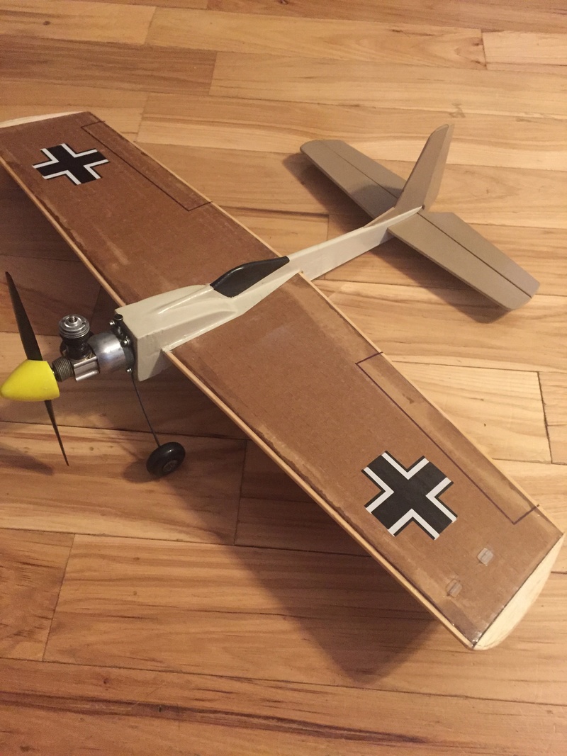
I liked those models a LOT.. and I'm glad to be a catalyst to get you inspired to build again!


 engine-mount/nose-reinforcement
Trying to K.I.S. here.. but I'm also designing on the fly.. using materials that I have in stock. I need to provide some space for an external fuel-supply (tank) for the Cox .049 product-engine option. The "cheek-blocks" found in some traditional 1/2A profile kit-designs for reed-valve engines prohibit this. As in my previous designs, I use the vertical hardwood-blocks combined with plywood nose-doublers to form a rigid "T" engine-mounting which leaves some room behind the mounting, for a hard-tank.
I'm marking-up the drawing as I go.. and will compile a "stock-list" on completion.

I'm marking-up the drawing as I go.. and will compile a "stock-list" on completion.
 Re: Another proposed design by Roddie
Its getting assembled!!!! Looking good. So if I am not mistaking, it is a 1/4" fuselage with 1/16" doublers on the sides? I now understand the 'ridgid t' as mentioned earlier. Looks good and strong up there.

NEW222- Top Poster

- Posts : 3896
Join date : 2011-08-14
Age : 46
Location : oakbank, mb
 Re: Another proposed design by Roddie
NEW222 wrote:Its getting assembled!!!! Looking good. So if I am not mistaking, it is a 1/4" fuselage with 1/16" doublers on the sides? I now understand the 'ridgid t' as mentioned earlier. Looks good and strong up there.
Yes it is! Thanks again Chancey!! The fuse is actually 3/16" (4.76mm) thickness balsa. It's relatively dense-wood though.. or else I would have chosen thicker stock. It's a combination of "B and C-grain".. which is what you'd want to use where strength is a consideration.. but not overkill/hard-grade wood.. which can be heavy. The nose-doublers are listed on my drawing as 1/16" plywood.. but I actually used a "single-ply" of .055" (1.4mm) Baltic-Birch.. as an experimental material. You won't find it for sale anywhere though. The material is "scrap".. procured from a CNC machining-process where I work. If you desire some of this stock, I have plenty that I could mail to you. It is also the stock that I am using (laminating x2 thicknesses; cross-grain) for the firewall.
The "rigid T"...
 Re: Another proposed design by Roddie
roddie wrote: but it will hopefully contain the engine to the airframe, if the model meets terra firma in a "less than graceful manner"..
Hi again roddie. I am in no way saying to do this, but just an idea I have used before. I cannot say or guarantee that it does work 100%, but does add strength to the engine mounts. Where the light blue 'X' is, drill a hole of proper size right through the upright engine mounts (this includes through the fuselage as well). From there, insert your choice of bracing (red line in picture above the 'X;'). I have used both hard wood toothpicks as well as bamboo skewers (this is why I said drill accordingly). I fill the hole with either epoxy or wood glue, then insert my brace of choice and allow to dry. When dry, just cut off the ends and sand flush. To me, it is extra security for holding things to the fuselage. I would do one brace above the wing, and one brace below the wing. This is just my $.02.


NEW222- Top Poster

- Posts : 3896
Join date : 2011-08-14
Age : 46
Location : oakbank, mb
 fuse-contouring using the French-curve
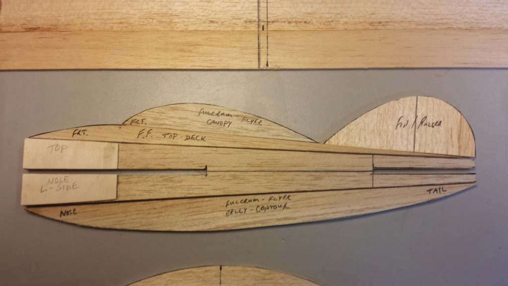
Here's an example of what I came up with for adding contours to the fuse, using a French-curve.
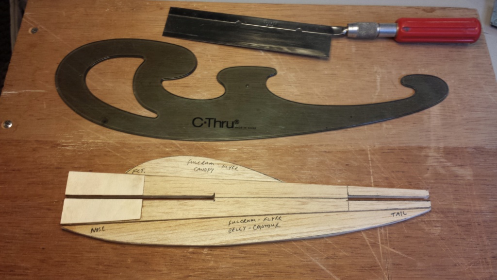
The top-side of the nose; fairing back-into the canopy, needs a little attention.. but I'm satisfied with the general shape so far. There's still the fin/rudder to draw-out. I'm leaning toward a Ringmaster-shape.
Choosing belly/canopy contours takes no time at all.. nor does drawing (tracing) them onto the wood. " Cutting-out and sanding" the parts takes a little more time.. but that's modeling..
Last edited by roddie on Sat Feb 09, 2019 3:45 am; edited 1 time in total
 Re: Another proposed design by Roddie
NEW222 wrote:roddie wrote: but it will hopefully contain the engine to the airframe, if the model meets terra firma in a "less than graceful manner"..
Hi again roddie. I am in no way saying to do this, but just an idea I have used before. I cannot say or guarantee that it does work 100%, but does add strength to the engine mounts. Where the light blue 'X' is, drill a hole of proper size right through the upright engine mounts (this includes through the fuselage as well). From there, insert your choice of bracing (red line in picture above the 'X;'). I have used both hard wood toothpicks as well as bamboo skewers (this is why I said drill accordingly). I fill the hole with either epoxy or wood glue, then insert my brace of choice and allow to dry. When dry, just cut off the ends and sand flush. To me, it is extra security for holding things to the fuselage. I would do one brace above the wing, and one brace below the wing. This is just my $.02.
I LIKE that idea Chancey! I will definitely consider it!

 more contouring, cutting and sanding..

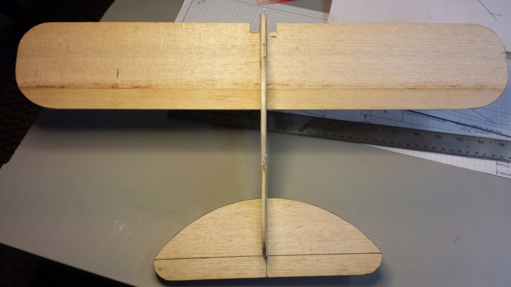
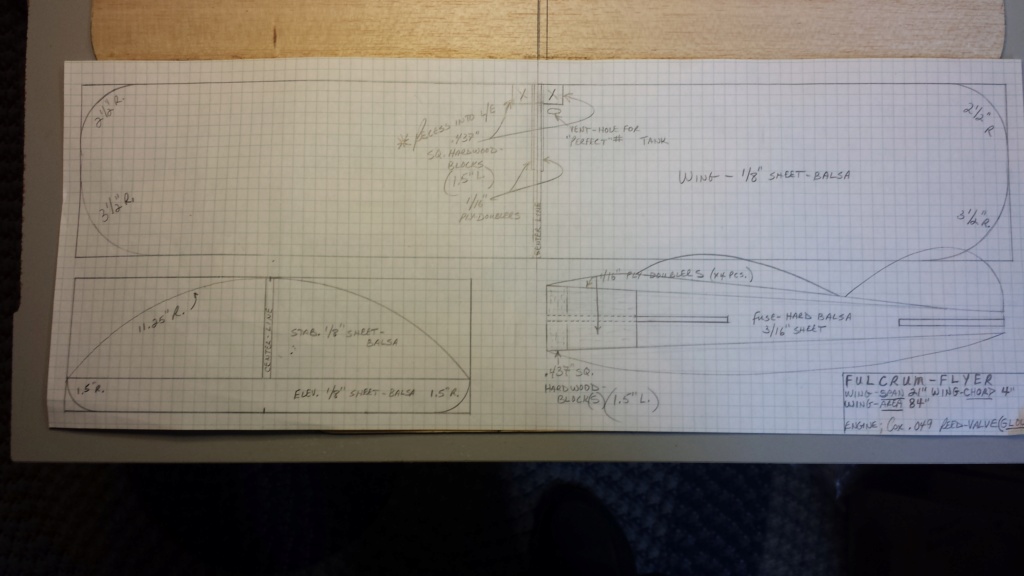
I keep adding details to my drawing.. once I make them to the physical model. As you can see.. it's getting cluttered. I will probably re-draw the whole design using a larger pc. of paper. I use a good quality "graph-paper" because it holds-up to repeated "erasing".. and helps with measuring and squaring-up outlines. I use Scotch (Magic-Tape) on the backside-seams when using multiple sheets. Sometimes the sheet-edge(s) need to be "trimmed" so that the 1/4" grid-patterns intersect accurately. This is important when using the grid to measure across multiple sheets.

getback- Top Poster


Posts : 10442
Join date : 2013-01-18
Age : 67
Location : julian , NC
 Re: Another proposed design by Roddie
getback wrote:What the heck is up with all the added fuse material ? I have a stunt man 23 and it dont look nothing like that , what is the weight. Sorry butt it was looking good till (well)
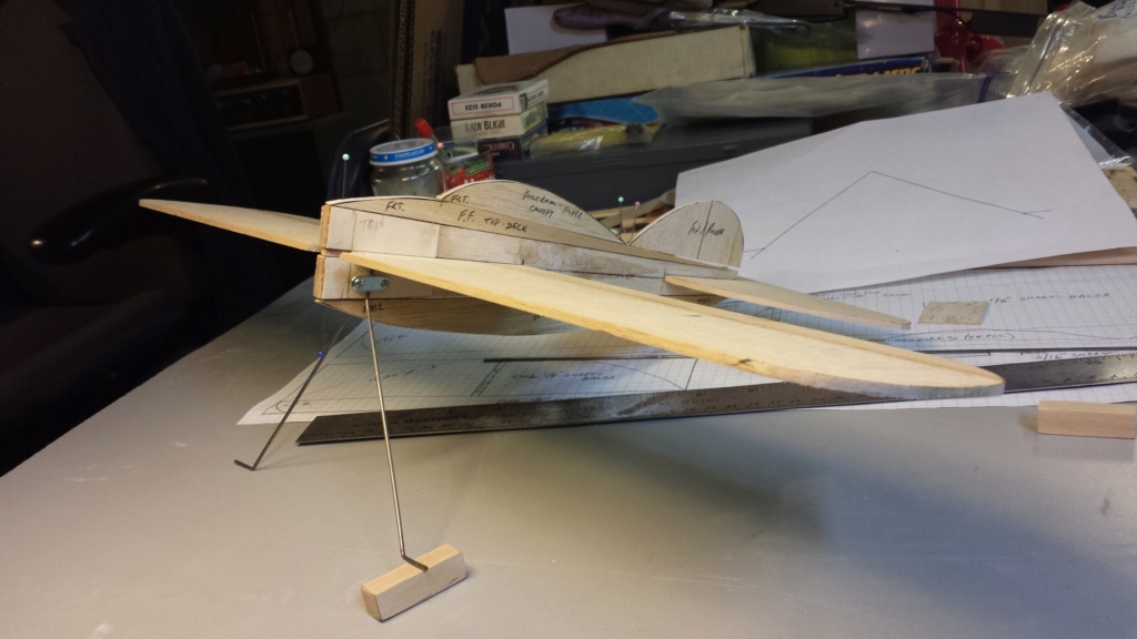
The weight (less wheels and paint) is 4.5 oz.

It's difficult to see in the above photo, but there's a 16+ inch piece of .062" music-wire on the scale which weighs .2 oz. I included it because the elev. pushrod will be made from it.. but at "half" that length.
I appreciate your honesty Eric.
 Re: Another proposed design by Roddie
Eric, you are precious. Bet you have never been told that. Me neither. You ever leave the forum I'm following you out the door.
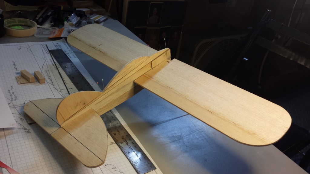
roddie I like your design but the horizontal stab doesn't come close to matching the wing. But, beauty is in the eye. I love the notations, I would be tempted to clear gloss them over and keep them. Adds uniqueness and charm.
Keep at it, you have never made a dud yet.
Bob
PS: Eric, the paint scheme on your plane is just plain awful.

rsv1cox- Top Poster


Posts : 11251
Join date : 2014-08-18
Location : West Virginia
 Re: Another proposed design by Roddie
Oooooh. Added body parts! I like the thought, and changes. I wish I had the mindset to do something like that. Now as I see it with your added cut-outs, to me, it screams to me that it is like a cartoon type plane. I do like the shorter chubby style fuselage design, and that is where I see the 'cartoon' in it. Keep up teh good work, I'm enjoying it! I really like every little twist along the way.

NEW222- Top Poster

- Posts : 3896
Join date : 2011-08-14
Age : 46
Location : oakbank, mb
 Re: Another proposed design by Roddie
Kari, I think you have it.
Just add a little positive inboard taper to the wing and it fits, even carries out roddies oval horz stab.
The Brewster Buffalo, has been a favorite of mine. Seems it saw action early WW2. Clearly out classed though by fighters of the period.
Just add a little positive inboard taper to the wing and it fits, even carries out roddies oval horz stab.
The Brewster Buffalo, has been a favorite of mine. Seems it saw action early WW2. Clearly out classed though by fighters of the period.

rsv1cox- Top Poster


Posts : 11251
Join date : 2014-08-18
Location : West Virginia
 Re: Another proposed design by Roddie
The Buffalo is one of my favourites too. Its world-wide signifigance is not very big, but it is the fighter that saved Finland in the beginning of the Continuation War against the Soviets. They did pretty good actually, of course the Soviets did not have their best and most experienced forces at our front.
Here’s one of the Aces, Hans Wind (yes, that’s his real name although it sounds like a some kind of a superhero nickname) with his Buffalo, note the kill markings on the tail.

Here’s one of the Aces, Hans Wind (yes, that’s his real name although it sounds like a some kind of a superhero nickname) with his Buffalo, note the kill markings on the tail.


KariFS- Diamond Member

- Posts : 2044
Join date : 2014-10-10
Age : 53
 Re: Another proposed design by Roddie
rsv1cox wrote:Eric, you are precious. Bet you have never been told that. Me neither. You ever leave the forum I'm following you out the door.
roddie I like your design but the horizontal stab doesn't come close to matching the wing. But, beauty is in the eye. I love the notations, I would be tempted to clear gloss them over and keep them. Adds uniqueness and charm.
Keep at it, you have never made a dud yet.
Bob
PS: Eric, the paint scheme on your plane is just plain awful.


 OK i did say i was SORRY ! Hold on and i will take another look
  There thats alot better . Just saying I know i built and painted ? that 23 when i was like 15 Its still in one piece . Roddie you the Man Whatever you decide is fine with me

getback- Top Poster


Posts : 10442
Join date : 2013-01-18
Age : 67
Location : julian , NC
 Re: Another proposed design by Roddie
getback wrote:rsv1cox wrote:Eric, you are precious. Bet you have never been told that. Me neither. You ever leave the forum I'm following you out the door.
roddie I like your design but the horizontal stab doesn't come close to matching the wing. But, beauty is in the eye. I love the notations, I would be tempted to clear gloss them over and keep them. Adds uniqueness and charm.
Keep at it, you have never made a dud yet.
Bob
PS: Eric, the paint scheme on your plane is just plain awful.

OK i did say i was SORRY ! Hold on and i will take another look
There thats alot better . Just saying I know i built and painted ? that 23 when i was like 15 Its still in one piece . Roddie you the Man Whatever you decide is fine with me

roddie, back to you.
Bob

rsv1cox- Top Poster


Posts : 11251
Join date : 2014-08-18
Location : West Virginia
 Re: Another proposed design by Roddie
Thank You "all" for commenting. I appreciate it very much. Yes.. I tend to apply some unorthodox styling-cues and unconventional construction techniques to my models. There's often challenges along the way.. but there's always a way around them. Solving problems is something that I find enjoyable.. rather than getting frustrated. It does take patience.. of which I have a lot of.
 .... hinging the stab./elev.
Most of you have seen me use this technique for CA-hinges before.. but I'll reiterate/post photos for those who haven't.
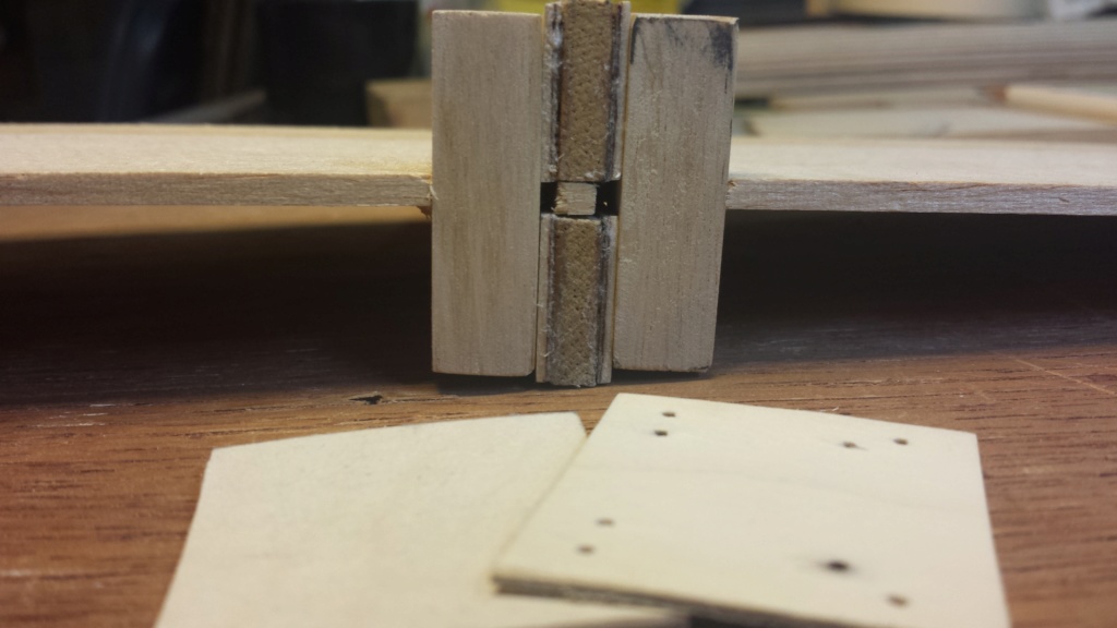
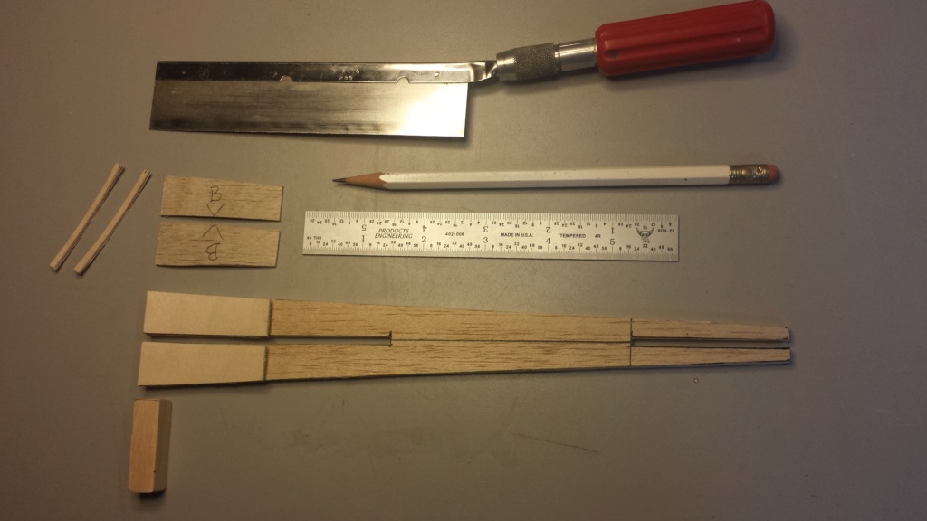
My control-surfaces to be hinged are 1/8" balsa. I layout the hinge-points using a scale.. prior to separating (cutting) the stab./elev. apart into two separate pieces. This assures that the hinge-points line-up on both parts.
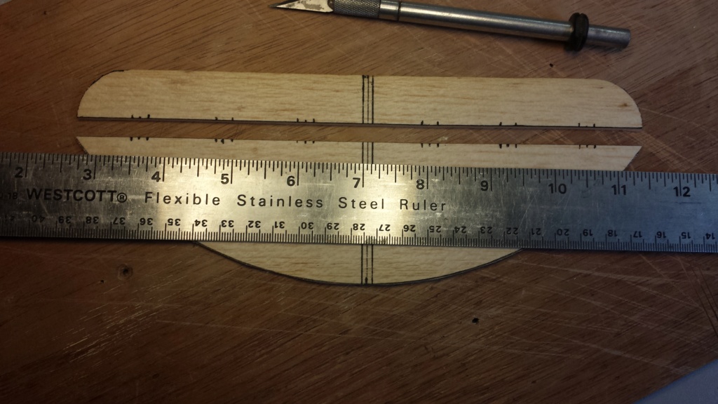
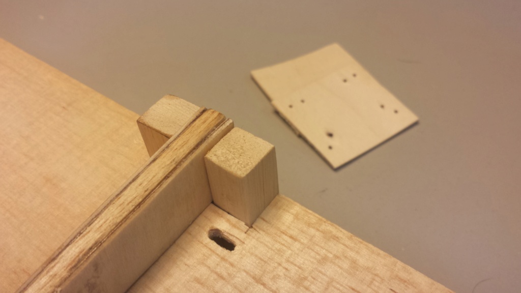
I like the "Sig Manufacturing" brand Easy Hinges. They are inserted into a "slot" in the control-surface and held secure with thin CA-glue. Each hinge measures 3/4" x 1" for larger models.. so I cut them into 1/4" x 3/4" pieces for my 1/2A airplanes. I use an x-acto #17 chisel-blade to cut the hinge-slots.
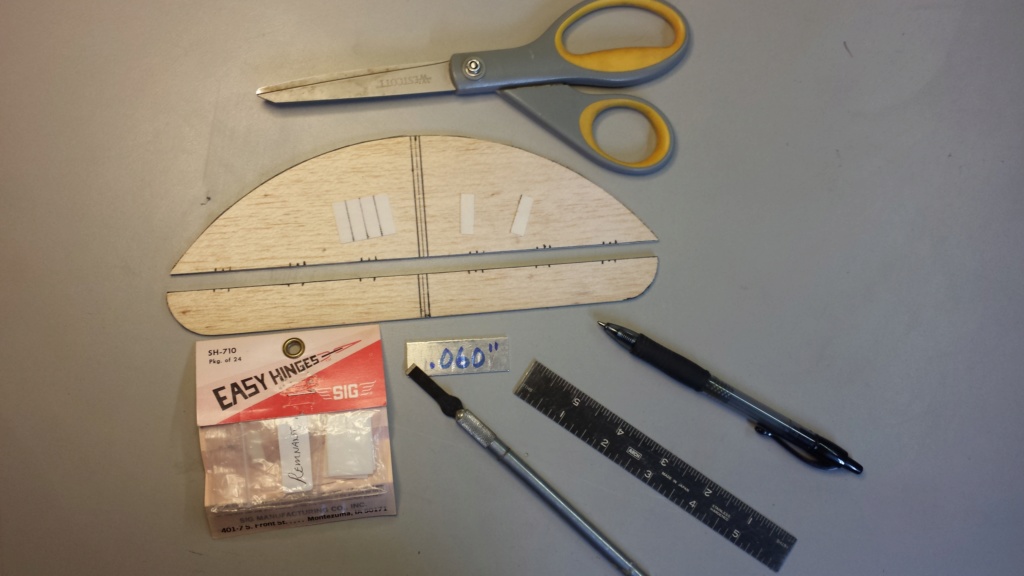
After cutting the hinges to 1/4" x 3/4" I "nibble" the corners diagonally with clippers. This makes the hinge easier to install into the slot.

For slotting 1/8" thickness control-surfaces, I use a half-thickness (1/16") strip of material. It could be 1/16" plywood.. or anything else.. as long as it's half the thickness of the control surfaces to be hinged. The #17 chisel-blade is laid-flat against the strip and up against the edge of the control-surface, which centers the blade for cutting the slot. It helps to clamp the workpiece close to the edge of a tabletop for better control of the tool.. and cutting-depth.

Then the hinges are "dry-fitted" (no glue yet!!!)


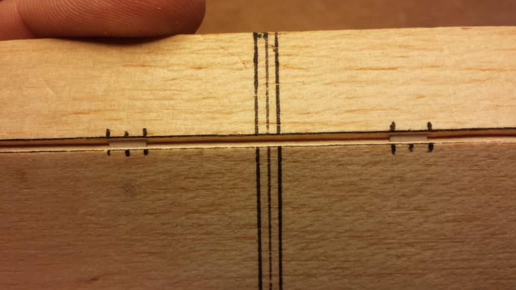
Once the dry-fitting is done, the hinges are removed and the surfaces get "beveled" (sanded) to a feathered-edge.
My control-surfaces to be hinged are 1/8" balsa. I layout the hinge-points using a scale.. prior to separating (cutting) the stab./elev. apart into two separate pieces. This assures that the hinge-points line-up on both parts.

I like the "Sig Manufacturing" brand Easy Hinges. They are inserted into a "slot" in the control-surface and held secure with thin CA-glue. Each hinge measures 3/4" x 1" for larger models.. so I cut them into 1/4" x 3/4" pieces for my 1/2A airplanes. I use an x-acto #17 chisel-blade to cut the hinge-slots.

After cutting the hinges to 1/4" x 3/4" I "nibble" the corners diagonally with clippers. This makes the hinge easier to install into the slot.

For slotting 1/8" thickness control-surfaces, I use a half-thickness (1/16") strip of material. It could be 1/16" plywood.. or anything else.. as long as it's half the thickness of the control surfaces to be hinged. The #17 chisel-blade is laid-flat against the strip and up against the edge of the control-surface, which centers the blade for cutting the slot. It helps to clamp the workpiece close to the edge of a tabletop for better control of the tool.. and cutting-depth.

Then the hinges are "dry-fitted" (no glue yet!!!)


Once the dry-fitting is done, the hinges are removed and the surfaces get "beveled" (sanded) to a feathered-edge.
 Re: Another proposed design by Roddie
Wow roddie. That looks great. I love the hinging method. I have used them in the past but they were almost never straight into the surface. Sometimes even poking through the surface. A nice and easy idea. Thanks. However, I have to ask. Do you feel the control surface is too stiff? I used to use strips of them as you, but thought they were too stiff for my liking. I have heard of old computer floppy disks, but never tried them. All the best!

NEW222- Top Poster

- Posts : 3896
Join date : 2011-08-14
Age : 46
Location : oakbank, mb
 Re: Another proposed design by Roddie
Chancey, I used to use the sm. size Dubro pinned-hinges.. and cut the slots for them using the Dubro "Kwik-Hinge Slotter" tool. The pinned-hinges are nice.. but digging-out the slots for them is a wicked PIA. My first four designs from back in the 1990's have them. It's a wonder that I built any more models after that..  By the fourth one.. I had gotten better at it.. (my flapped orange plane has ten Dubro sm. pinned-hinges..) but once I tried the Sig CA hinges.. I never looked back.
I've wanted to try the "stitched-hinge".. and probably should have with this design.. but I'm used to the technique that I've developed with the CA type. Yea.. they're stiffer but I don't think it's a big deal. I fly control-line.. and I actually like the feedback at the handle.. if that makes sense. A 1/2A RC flyer might be concerned about the stresses that stiffer hinges might place on small/nano-servos.. but in reality; poorly-configured (binding) control-linkages pose more of a threat to a servo. IMHO..
Thanks again for your support!
Page 2 of 7 •  1, 2, 3, 4, 5, 6, 7
 Similar topics
» Roddie's CEF 2019 "RWYB" proposed entry(ies)..
» New P-38 profile scratch build log
» Roddie-Rigger.. a 2005 original design
» Cox Engines - Proposed Users
» CEF speed contest Design Discussions
» New P-38 profile scratch build log
» Roddie-Rigger.. a 2005 original design
» Cox Engines - Proposed Users
» CEF speed contest Design Discussions
Page 2 of 7
Permissions in this forum:
You cannot reply to topics in this forum

 Rules
Rules

