Log in
Search
Latest topics
» TEE DEE Having issuesby balogh Today at 2:42 pm
» Retail price mark-up.. how much is enough?
by rsv1cox Today at 2:36 pm
» Cox films/videos...
by Coxfledgling Today at 11:46 am
» Purchased the last of any bult engines from Ken Enya
by Coxfledgling Today at 11:18 am
» My N-1R build log
by roddie Today at 7:32 am
» Happy 77th birthday Andrew!
by akjgardner Today at 7:27 am
» Landing-gear tips
by roddie Today at 1:17 am
» Roger Harris revisited
by TD ABUSER Yesterday at 9:13 pm
» Tee Dee .020 combat model
by Ken Cook Yesterday at 8:41 pm
» My latest doodle...
by roddie Yesterday at 5:43 pm
» Chocolate chip cookie dough.........
by roddie Fri Nov 22, 2024 8:13 pm
» Free Flight Radio Assist
by rdw777 Fri Nov 22, 2024 4:24 pm
Cox Engine of The Month
Another proposed design by Roddie
Page 4 of 7
Page 4 of 7 •  1, 2, 3, 4, 5, 6, 7
 re-drawing the plan..
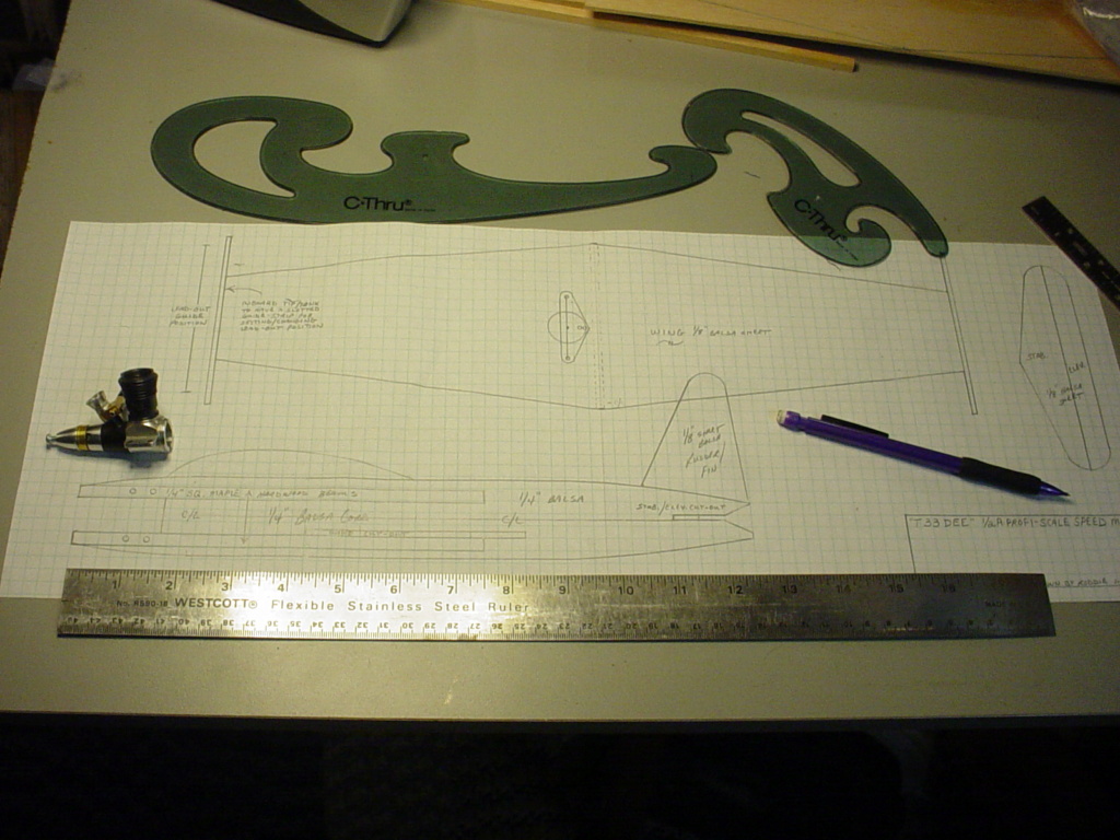
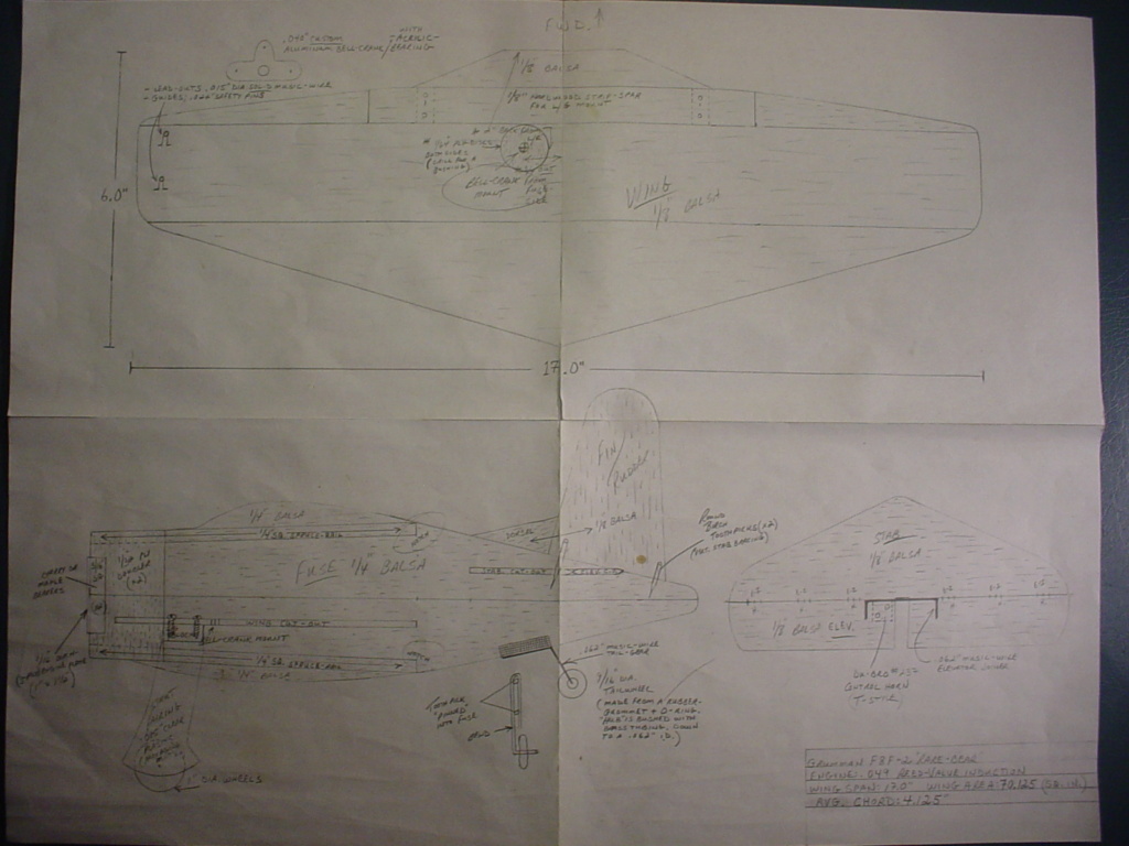
Earlier today.. I taped-together four sheets of graph-paper in anticipation of re-drawing this airplane design. The single-sheets measure 8.5" x 11.75". I laid them out in a 17" x 23.5" configuration. The overall dimensions can be as much as 1/2" less, because of the trimming needed on the sheet-borders for the grid-patterns to intersect accurately.
I use "Scotch" Magic-Tape on the backside-seams to join the sheets together.
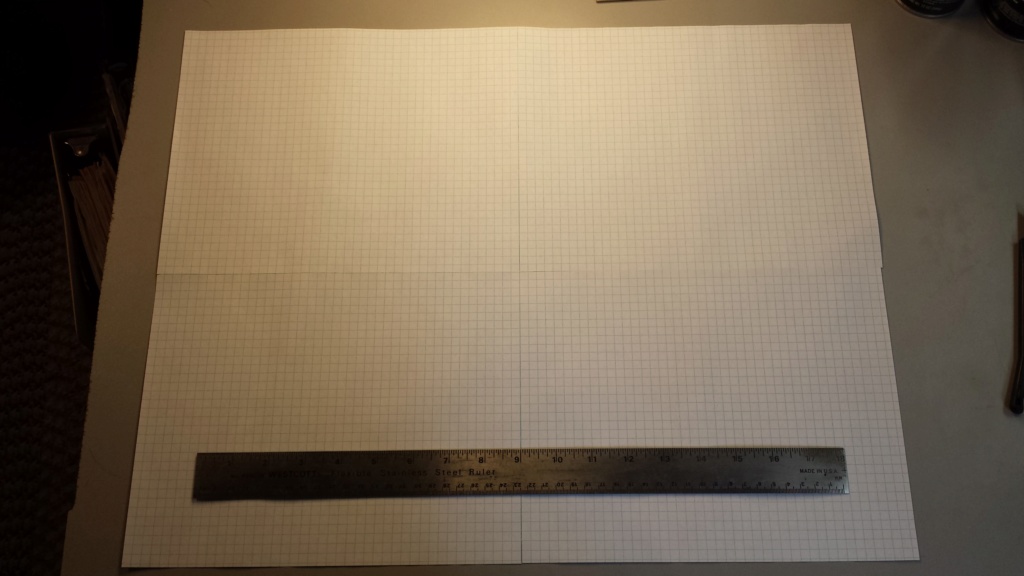
This models' 21" wing-span just fits into this format..
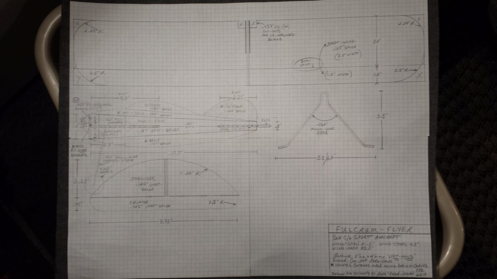
I do have a habit of drawing-out my designs prior to any flight-testing.. but if I waited to fly the airplane.. the plan would never be drawn..
I use "Scotch" Magic-Tape on the backside-seams to join the sheets together.

This models' 21" wing-span just fits into this format..

I do have a habit of drawing-out my designs prior to any flight-testing.. but if I waited to fly the airplane.. the plan would never be drawn..
 Re: Another proposed design by Roddie
Those are well documented. I like your method of doing it on graph paper. Nice and easy to keep things straight. I don't know which I like best, as they all look great and well done.

NEW222- Top Poster

- Posts : 3896
Join date : 2011-08-14
Age : 46
Location : oakbank, mb
 Re: Another proposed design by Roddie
NEW222 wrote:Those are well documented. I like your method of doing it on graph paper. Nice and easy to keep things straight. I don't know which I like best, as they all look great and well done.
Hey.. thanks Chancey!
 I appreciate that. The way I see it; I'll be gone someday.. and who-knows when. My models might not fly worth a damn.. but someone may want to build one of my designs someday.. just for fun. A drawing tends to last a lot longer than a model does.
  Epoxy.. it's messy but it's strong...
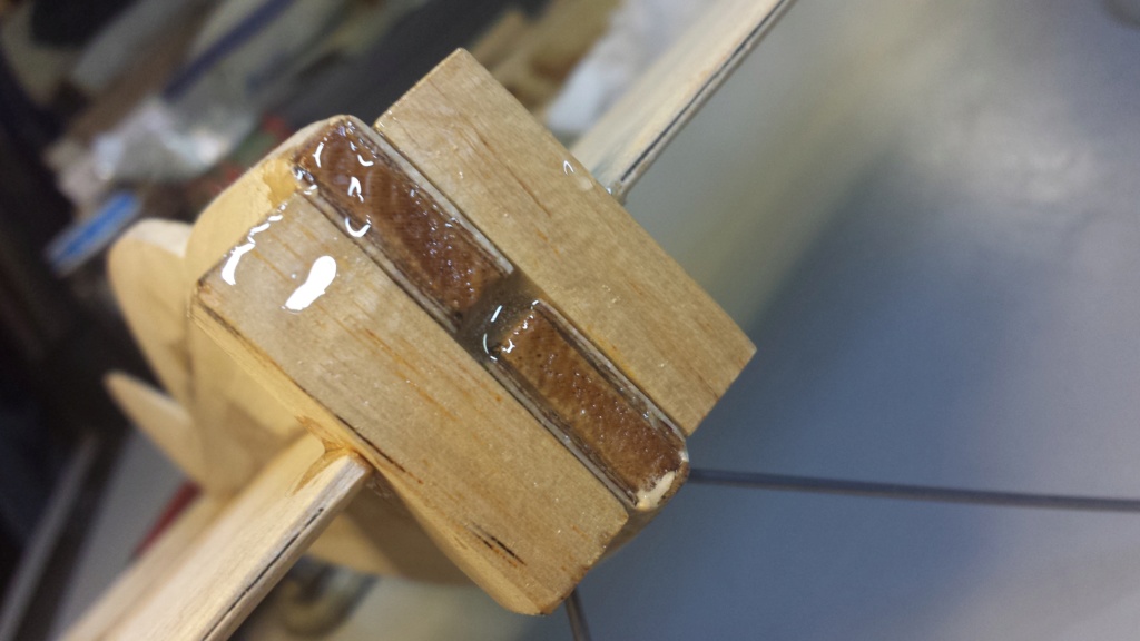
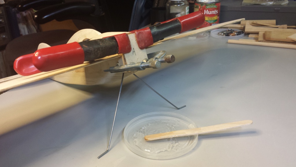
I use epoxy where extra-strength is needed in a joint. Typically.. I use it in the nose-construction of my models. Tonight I installed/glued-up the nose-blocks for this model. This was a different-install.. in that the nose-blocks needed to be glued-in after the wing was installed. The plywood firewall-panels will be glued onto the nose-blocks.. after the nose-block glue has cured.
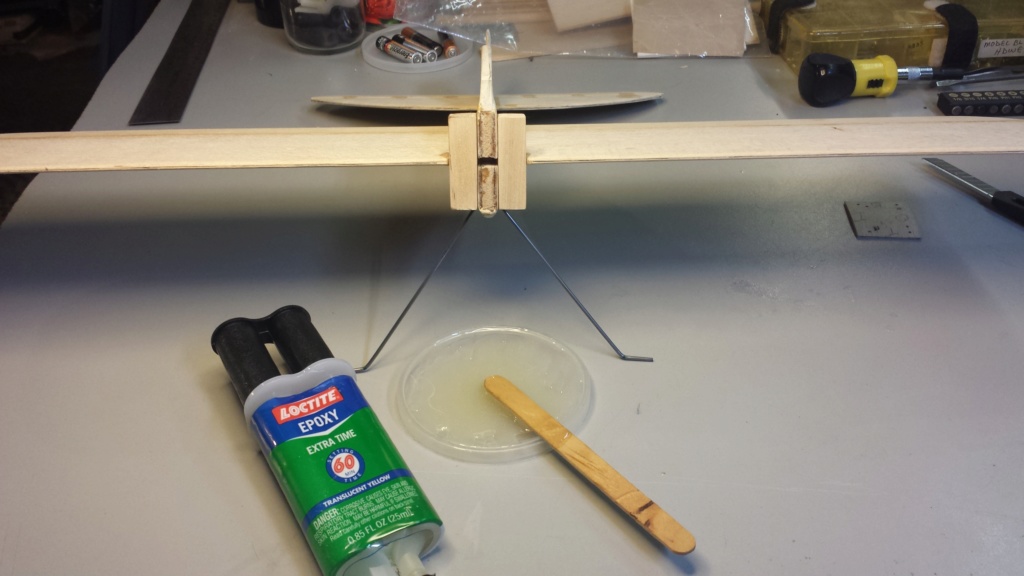

I may "pin" the nose-blocks.. as CEF member New222 (Chancey) recommended. More on that later..


I may "pin" the nose-blocks.. as CEF member New222 (Chancey) recommended. More on that later..
Last edited by roddie on Sat Feb 23, 2019 9:09 pm; edited 1 time in total (Reason for editing : added photos 2/23/19)
 "building" a bellcrank..
You may ask "why" build a bellcrank..  It's not an easy task to source a small/half-A size bellcrank these days. I will admit that I had access to a CNC router-machine a few years ago.. and took the liberty of cutting some .040" aluminum bellcrank "blanks" in three sizes. (S-M-L) I chose the "medium" size for this model. It has a 1.625" lead-out spacing.
I'll be using .015" braided-line for the lead-outs.
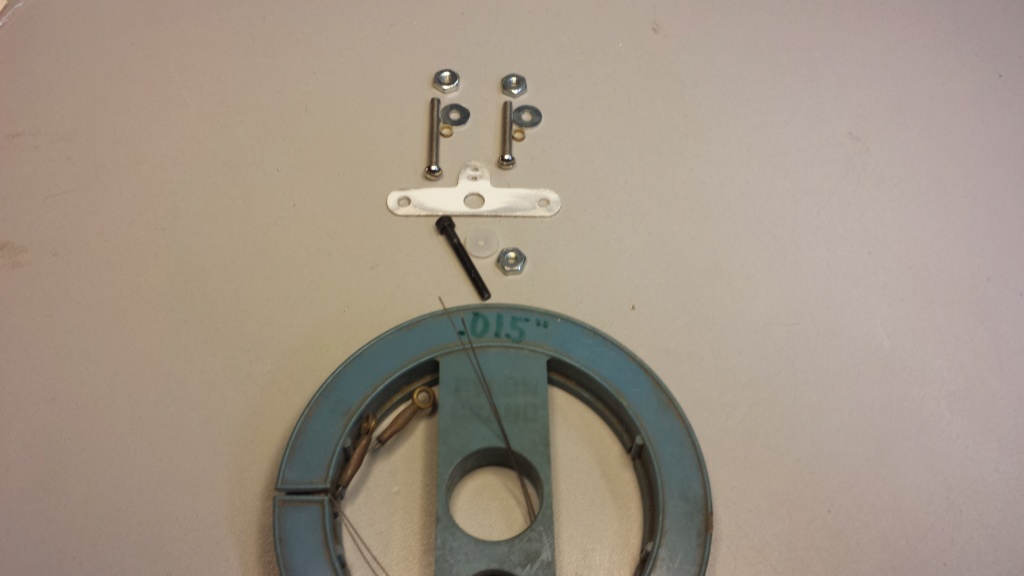
Stay-tuned...
 It's not an easy task to source a small/half-A size bellcrank these days. I will admit that I had access to a CNC router-machine a few years ago.. and took the liberty of cutting some .040" aluminum bellcrank "blanks" in three sizes. (S-M-L) I chose the "medium" size for this model. It has a 1.625" lead-out spacing.
I'll be using .015" braided-line for the lead-outs.

Stay-tuned...
 Re: Another proposed design by Roddie
roddie wrote:You may ask "why" build a bellcrank..It's not an easy task to source a small/half-A size bellcrank these days. I will admit that I had access to a CNC router-machine a few years ago.. and took the liberty of cutting some .040" aluminum bellcrank "blanks" in three sizes. (S-M-L) I chose the "medium" size for this model. It has a 1.625" lead-out spacing.
I'll be using .015" braided-line for the lead-outs.
Stay-tuned...
I will be watching this part closely as well. I like the homemade bellcrank and have made a couple myself so far and have to make another shortly for another plane. I will post a new topic on that later today. However, I am always uncertain on how exactly to mount the bellcrank. Unlike the factory nylon ones supplied in the 1/2a kits or even in the larger .35 size kits that have a nylon bushing that does all the work for you. I do not mean the actual mounting location, but rather what is used for screws/pin and how to hold teh bellcrank in place. Looking better and better with every picture.

NEW222- Top Poster

- Posts : 3896
Join date : 2011-08-14
Age : 46
Location : oakbank, mb
 Re: Another proposed design by Roddie
NEW222 wrote:roddie wrote:You may ask "why" build a bellcrank..It's not an easy task to source a small/half-A size bellcrank these days. I will admit that I had access to a CNC router-machine a few years ago.. and took the liberty of cutting some .040" aluminum bellcrank "blanks" in three sizes. (S-M-L) I chose the "medium" size for this model. It has a 1.625" lead-out spacing.
I'll be using .015" braided-line for the lead-outs.
Stay-tuned...
I will be watching this part closely as well. I like the homemade bellcrank and have made a couple myself so far and have to make another shortly for another plane. I will post a new topic on that later today. However, I am always uncertain on how exactly to mount the bellcrank. Unlike the factory nylon ones supplied in the 1/2a kits or even in the larger .35 size kits that have a nylon bushing that does all the work for you. I do not mean the actual mounting location, but rather what is used for screws/pin and how to hold teh bellcrank in place. Looking better and better with every picture.
Hey Chancey!!! I hope that I can help you figure-out a few things here. Regarding the "mounting" of the bellcrank; be sure that there's hardwood surrounding the mount. There's generally "one screw" for the pivot. Be sure that it is supported adequately.
It's in your best interest to source some very thin plywood for your 1/2A C/L models. You'll use it for "fuse-doublers" on profile-designs.. as well as bellcrank-platforms.
Many years ago... I sourced some model-plywood from Sig Manufacturing Co. I bought x1 sheet 12" x 24" x 1/32" thickness plywood.. and x1 sheet of 12" x 24" x 1/64" thickness plywood. It's expensive.. until you calculate how much you need for a particular-purpose.
When your flying-models get smaller.. it's imperative that you build light... and strong.. if permissible..
 engine-mount
A little more work on the engine-mount. I cut three pieces of 1/32" plywood and laminated them together to make a firewall. The 3/32" (.094") thickness seemed like a good compromise between 1/16" and 1/8".
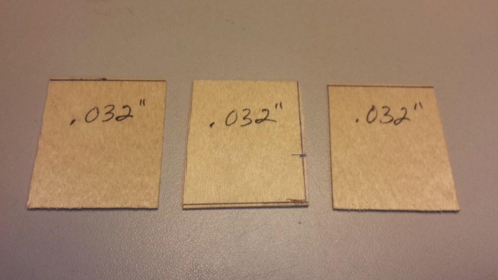
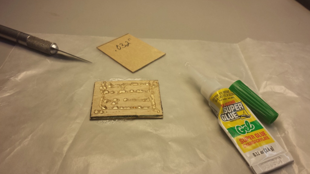
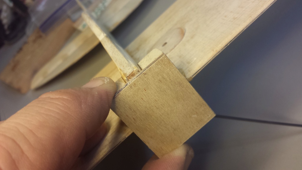
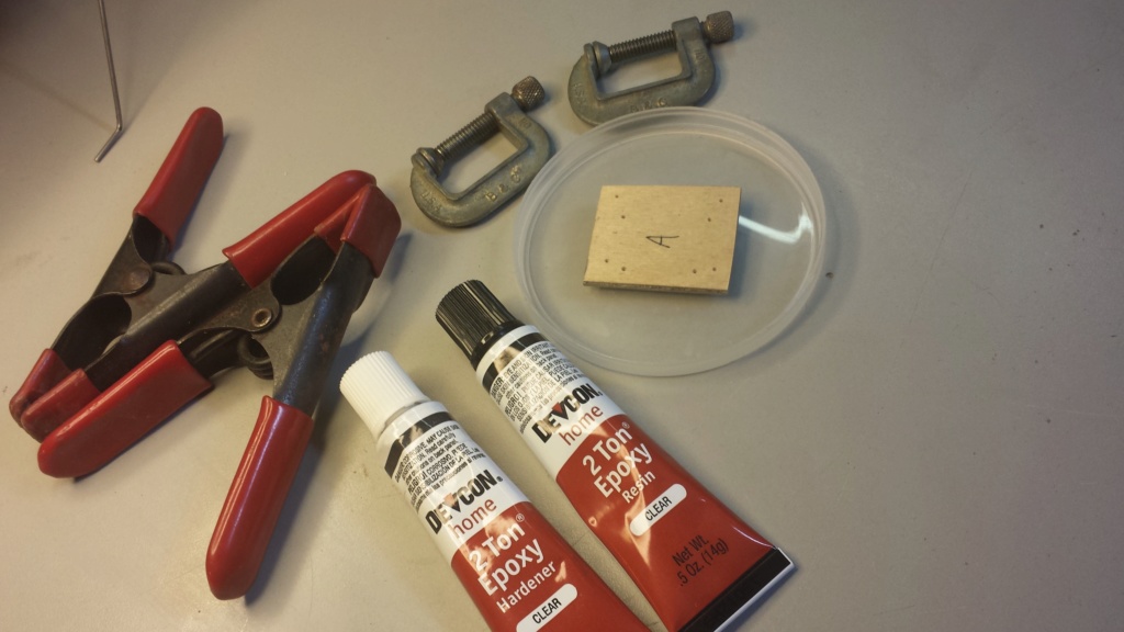
I used a different epoxy for bonding to the hardwood nose-blocks.
I made punch-marks for the Cox .049 "Bee" engines and also for the horseshoe backplate/mount of the "product-engine".. but I should have marked the beam-locations, because the "horizontally-oriented" horseshoe mounting-pattern was off-center with the beams. This can be seen in the photo below.. (the first punch-marks for the horseshoe-pattern were too far to the left)
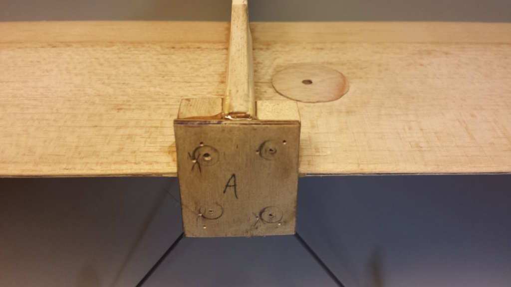
Luckily I noticed prior to drilling the screw-holes. I plan on using a product-engine configuration.. and did not drill the "Bee" mount-pattern.
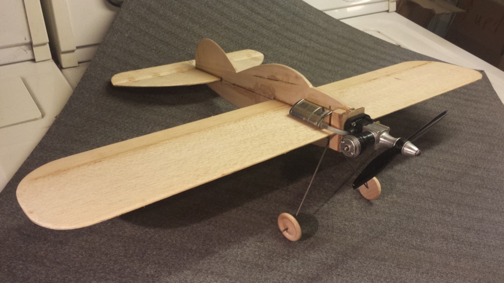
If the model happens to end-up tail-heavy.. I'll have the option of swapping to a "Golden Bee" .049 which moves a considerable amount of weight forward.


I used a different epoxy for bonding to the hardwood nose-blocks.


I made punch-marks for the Cox .049 "Bee" engines and also for the horseshoe backplate/mount of the "product-engine".. but I should have marked the beam-locations, because the "horizontally-oriented" horseshoe mounting-pattern was off-center with the beams. This can be seen in the photo below.. (the first punch-marks for the horseshoe-pattern were too far to the left)

Luckily I noticed prior to drilling the screw-holes. I plan on using a product-engine configuration.. and did not drill the "Bee" mount-pattern.

If the model happens to end-up tail-heavy.. I'll have the option of swapping to a "Golden Bee" .049 which moves a considerable amount of weight forward.
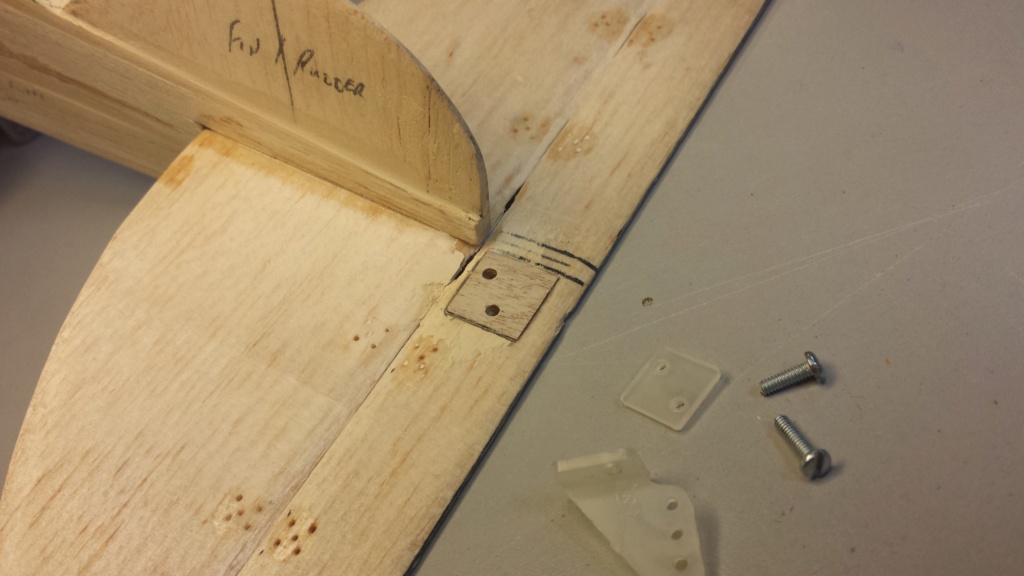
 reinforcing the control-horn mount
I had previously butchered the horn-mount and had to fill and sand the holes and gouges from a screwdriver..  so.. I decided to reinforce the top/bottom of the elevator with 1/2" squares of 1/64" plywood. I should have done this from the beginning. The plywood will also help to prevent the underlying balsa from crushing when the horn is assembled.

 Re: Another proposed design by Roddie
Looking really good roddie. I also like that you used teh reinforcements on the tail for teh horn. I realized it in the past that tightning it would crush the wood. However, I had used 1/32 ply as it was what I happened to have on hand. Also, what is teh dry time of the epoxy you are using? I have both 5 and 30 minute epoxy that I use here.

NEW222- Top Poster

- Posts : 3896
Join date : 2011-08-14
Age : 46
Location : oakbank, mb
 Re: Another proposed design by Roddie
NEW222 wrote:Looking really good roddie. I also like that you used teh reinforcements on the tail for teh horn. I realized it in the past that tightning it would crush the wood. However, I had used 1/32 ply as it was what I happened to have on hand. Also, what is teh dry time of the epoxy you are using? I have both 5 and 30 minute epoxy that I use here.
Thank you Chancey! Many years ago I bought 1/64" and 1/32" plywood from Sig Manufacturing Co. in Iowa. Both sheets were 12" x 24". I've used it for many things.. and there's still a lot of it leftover.
The "Devcon" epoxy used on the firewall is 30 min. cure-time... and is clear/colorless. The blocks behind the firewall were glued with 60 min. "Loctite" brand which cures to a translucent yellow. I haven't used the 5 min. cure epoxy, but I do have some. It is also Loctite brand and cures translucent yellow. The Loctite epoxy's are both "plunger-style" dispensers. I don't really care for them. The 30 min. Devcon is two separate tubes.. which I find easier to work with.
 U-control linkage
This may look simple.. but it took me several hours to fabricate.. 
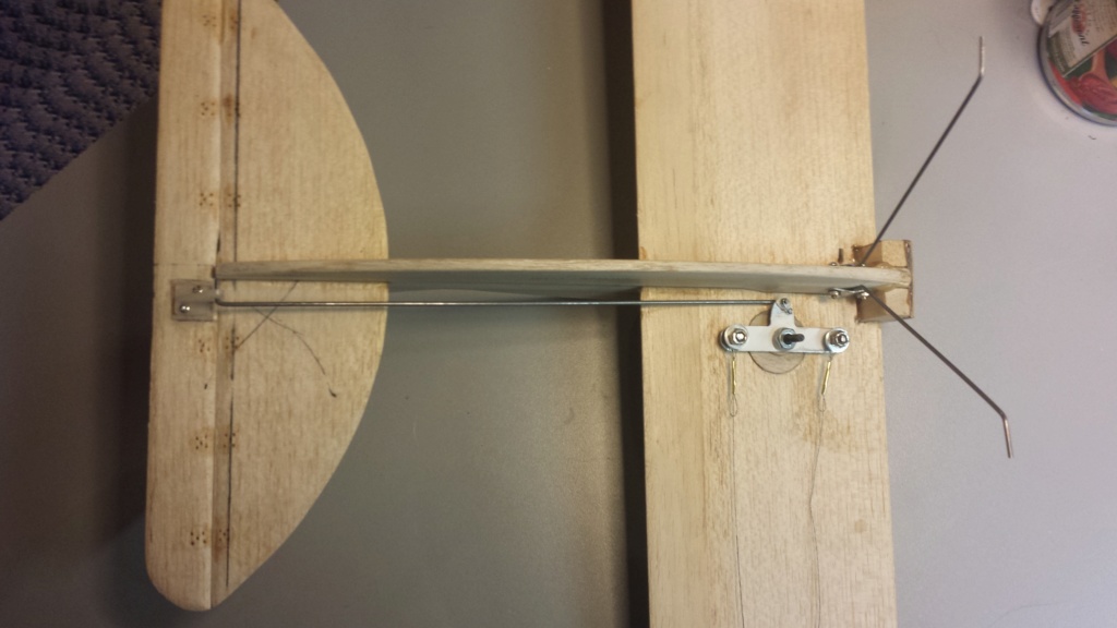
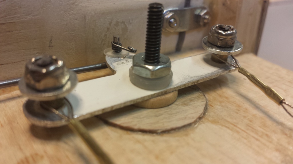
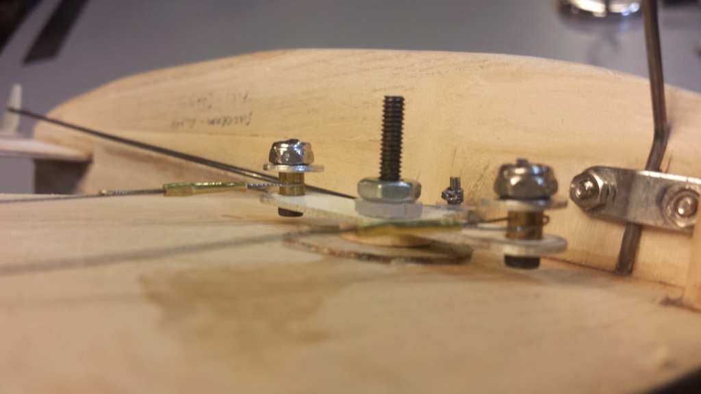
The #5-40 central pivot-screw will be cut-off flush with the hex-nut... and "thread-locker" applied at finish. The thimbles on the bellcrank are made from #3-48 cap-screws and 5/32" brass-tube bushings, small fender-washers with #3-48 lock-nuts retaining them. The lead-out cables were re-done using .015" braided SS line. I still need to work-out a guide-arrangement for the lead-outs.


The #5-40 central pivot-screw will be cut-off flush with the hex-nut... and "thread-locker" applied at finish. The thimbles on the bellcrank are made from #3-48 cap-screws and 5/32" brass-tube bushings, small fender-washers with #3-48 lock-nuts retaining them. The lead-out cables were re-done using .015" braided SS line. I still need to work-out a guide-arrangement for the lead-outs.
 Re: Another proposed design by Roddie
I'm liking it! I really like your way of attaching the leadouts to the bellcrank. I am thinking I have to try it one day. However, your last post makes me have to ask you a question.... Where on earth did you get the 3-48 cap screws? I have been looking for some to use on my Fox .15x as a couple of the screws stripped, and I have not had any luck locally. I have a couple regular screws to use, but would have preffered cap heads. Do you have a local screw supplier that stocks them? Even my LHS does not have any, and when I asked, they said they are not popular and were not used in modelling..... That is when I told him that a Fox engine used them. He just then proceeded to look at me.....

NEW222- Top Poster

- Posts : 3896
Join date : 2011-08-14
Age : 46
Location : oakbank, mb
 Re: Another proposed design by Roddie
3-48 screws are becoming obsolete. Due to requests Micro Fasteners has stocked a variety of sizes we use. They offer a small modellers pack in a plastic container with various sizes . They ship worldwide with a $7 minimum charge for shipping. They sell them in packages of 50 but as mentioned, they do have a variety package specifically for modellers.
Fox sold rebuild screw kits and gasket sets and had a billion of them. I would check with Mecoa. However, this may be just as costly as using Micro Fasteners. While the .15X used Phillips, the later gasket/screw sets were offered from Fox using allen cap screws.
Fox sold rebuild screw kits and gasket sets and had a billion of them. I would check with Mecoa. However, this may be just as costly as using Micro Fasteners. While the .15X used Phillips, the later gasket/screw sets were offered from Fox using allen cap screws.

Ken Cook- Top Poster

- Posts : 5641
Join date : 2012-03-28
Location : pennsylvania
 Re: Another proposed design by Roddie
NEW222 wrote:Where on earth did you get the 3-48 cap screws? I have been looking for some to use on my Fox .15x as a couple of the screws stripped, and I have not had any luck locally. I have a couple regular screws to use, but would have preffered cap heads. Do you have a local screw supplier that stocks them?
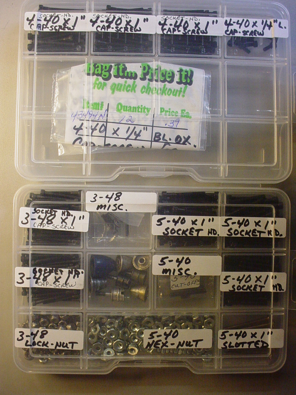
PM me your address Chancey.. and I'll mail you some. I sourced a box of "100" 3-48 x 1.000" length through a company called "Fastenal". I also sourced 4-40 and 5-40 x 1.000" length black-oxide cap-screws from that same company. I have glow-engines that use these sizes. The 6-32 and larger sizes are commonly available at local hdwe. stores in my area.
 Re: Another proposed design by Roddie
Thanks for the reply and help roddie.I have heard of fastenal, and will give them a look. I appreciate your offer, however, after looking at them on their site, they would not unfortunately work. I need all thread for the engine. But I will be coming back down in early April, and there is one in Grand Forks that I will be definitely visiting.

NEW222- Top Poster

- Posts : 3896
Join date : 2011-08-14
Age : 46
Location : oakbank, mb
 Re: Another proposed design by Roddie
Ken Cook wrote:3-48 screws are becoming obsolete. Due to requests Micro Fasteners has stocked a variety of sizes we use. They offer a small modellers pack in a plastic container with various sizes . They ship worldwide with a $7 minimum charge for shipping. They sell them in packages of 50 but as mentioned, they do have a variety package specifically for modellers.
Ken. As I've mentioned before, I'm not all that familiar with your US screw sizings, but having a truck load of American engines, I would be interested in getting an appropriate assortment that would suit my needs. I found the website you mentioned, but can't find any assortment that claims to be specific to modellers. Can you possibly suggest a good kit number to get from them?
Rod.

Oldenginerod- Top Poster

- Posts : 4018
Join date : 2012-06-16
Age : 62
Location : Drouin, Victoria
 Re: Another proposed design by Roddie
NEW222 wrote:Thanks for the reply and help roddie.I have heard of fastenal, and will give them a look. I appreciate your offer, however, after looking at them on their site, they would not unfortunately work. I need all thread for the engine. But I will be coming back down in early April, and there is one in Grand Forks that I will be definitely visiting.
I'm assuming that your Fox .15X may possibly need back-plate screws? I can't imagine what-else could possibly require "all-thread" on that engine. Certainly not the head.. ?

Here's a photo of the screw that I have.. against an inch scale/rule.
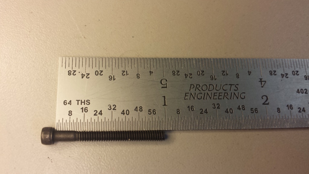
There's approx. 12/64" that's unthreaded under the head. Let me know if you think this screw might work.. and I'll mail you some asap.
Last edited by roddie on Wed Mar 06, 2019 4:28 am; edited 1 time in total
 Re: Another proposed design by Roddie
Yes roddie, I will be replacing all the screws. 4 on the head, and 2 on the backplate. I thank you for your time and help, however, it will not work due to the unthreaded part near the head. Now for the good news..... I made a call today to a place I forgot about. They do indeed have them in stock, however, there is a minimum purchase that will not be near meeting, but have something planned. The only unfortunate thing as well is I will not be able to make it there till mid April when I am on holidays as it is nowhere near my work, I carpool, as well as it would be close to being closed by time I would make it back. But I will get them! Thanks.

NEW222- Top Poster

- Posts : 3896
Join date : 2011-08-14
Age : 46
Location : oakbank, mb
 3-48
3-48
McMaster-Carr, https://www.mcmaster.com , carries 3-48 socket head screws in lengths from 1/8 to 1 1/4, they have no minimum order, but you do have to buy in boxes of 100. I get most all my hardware from them. They also have a large selection of metrics.

trebor3170- Moderate Poster

- Posts : 26
Join date : 2018-07-14
Age : 66
Location : Eastern Shore, MD
 pushrod-guide
not really a big deal.. but I took the time to make and install a pushrod guide tonight. It's made from a small safety-pin with the clasp cut off.
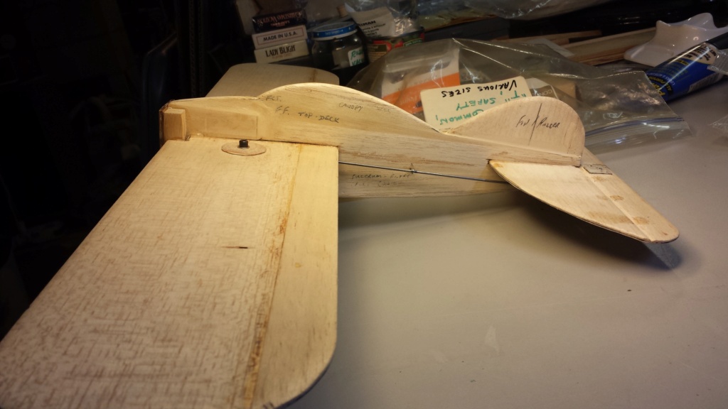
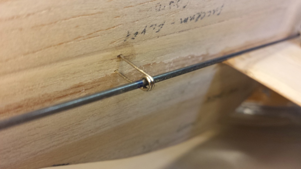
I inserted a "drill-bit" through the "eye" of the guide.. and then used needle-nose pliers to squeeze the two "legs" together until parallel. (the drill-bit keeps the safety-pins' eye concentric while applying force to the coil.) I trimmed the legs to the proper length.. and pressed them into the balsa, at the mid-point of the pushrod.. while the fuse was supported on the opposite side.
I then removed the guide and roughed-up the legs with an emery-board for better glue retention. I used thin CA glue to finally attach the guide.
The next step will be to make some small "fillets" at the wing and stabilizer roots. Then we'll almost be ready for the 1st coat of sealer/primer..

 Re: Another proposed design by Roddie
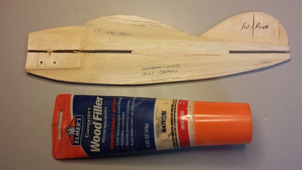
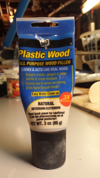
Just trucking along there on this. I had used wood filler befor, then it started getting harder as you mentioned, then since switched to drywall compound that I have laying around here. It seems to work alright anyways. Next step I guess is picking a paint scheme.....

NEW222- Top Poster

- Posts : 3896
Join date : 2011-08-14
Age : 46
Location : oakbank, mb
Page 4 of 7 •  1, 2, 3, 4, 5, 6, 7
 Similar topics
» Roddie's CEF 2019 "RWYB" proposed entry(ies)..
» New P-38 profile scratch build log
» Roddie-Rigger.. a 2005 original design
» Cox Engines - Proposed Users
» CEF speed contest Design Discussions
» New P-38 profile scratch build log
» Roddie-Rigger.. a 2005 original design
» Cox Engines - Proposed Users
» CEF speed contest Design Discussions
Page 4 of 7
Permissions in this forum:
You cannot reply to topics in this forum

 Rules
Rules


