Log in
Search
Latest topics
» Roger Harris revisitedby rsv1cox Today at 3:38 pm
» My N-1R build log
by GallopingGhostler Today at 3:04 pm
» Tee Dee .020 combat model
by 1/2A Nut Today at 2:43 pm
» Chocolate chip cookie dough.........
by roddie Today at 1:13 pm
» Purchased the last of any bult engines from Ken Enya
by sosam117 Today at 11:32 am
» Free Flight Radio Assist
by rdw777 Today at 9:24 am
» My latest doodle...
by batjac Yesterday at 9:47 pm
» Funny what you find when you go looking
by rsv1cox Wed Nov 20, 2024 3:21 pm
» Landing-gear tips
by 1975 control line guy Wed Nov 20, 2024 8:17 am
» Cox NaBOO - Just in time for Halloween
by rsv1cox Tue Nov 19, 2024 6:35 pm
» Canada Post strike - We are still shipping :)
by Cox International Tue Nov 19, 2024 12:01 pm
» Duende V model from RC Model magazine 1983.
by getback Tue Nov 19, 2024 6:08 am
Cox Engine of The Month
PeeWee, differences in SPI?
Page 1 of 1
 PeeWee, differences in SPI?
I've taken a closer look at some of my PeeWee engines and there seems to be a fairly large variation in the amount of SPI that these have. My most reliably running PeeWee is the one with the least amount of SPI... (if it is a coincidence or a real reason I don't know)
Was there any historical development here, e.g. did it change when they went from the thin cylinder walls to thicker ones?
At first I thought there was a difference in ports the cylinders, but it might actually lie in the height of the piston (or rather conrod length). I've measure a few spare pistons (unused) and they seem to vary a lot in terms of conrod length. With my rather inaccurate callipers I get a variation of about ±0.1 mm (=± 4/100 inch). Was the manufacturing really not more reliable than that?
I know that one should check and shim for a correct deck-height, but I could never imagine that it was that bad. Does anyone have any experience here?

Surfer_kris- Diamond Member

- Posts : 1912
Join date : 2010-11-20
Location : Sweden
 Re: PeeWee, differences in SPI?
Kris, can you tell if the pistons are flat across the top? Are you measuring with the caliper just on the edges of the skirt to the crown, or are you placing the caliper's forks across a wider cross section? I don't see any way they would wear towards a more developed SPI. Seems like it would wear toward less and the crowns may appear domed. Or a flat spot on top of the ball end of the rod.
Rusty
EDIT: I've never actually seen the inside parts of a Pee Wee, so I'm assuming it's the same architecture as an .049 Bee.
Rusty
EDIT: I've never actually seen the inside parts of a Pee Wee, so I'm assuming it's the same architecture as an .049 Bee.
_________________
Don't Panic!
...and never Ever think about how good you are at something...
while you're doing it!
My Hot Rock & Blues Playlist
...and never Ever think about how good you are at something...
while you're doing it!
My Hot Rock & Blues Playlist

RknRusty- Rest In Peace

- Posts : 10869
Join date : 2011-08-10
Age : 68
Location : South Carolina, USA
 Re: PeeWee, differences in SPI?
That's a strange phenomenon Kris. A more accurate way to help check what's going on, would be to obtain a depth micrometer. Install your subject cyl./piston/rod into the case and take readings on top of the piston at absolute-TDC. If you suspect differing length con-rods.. the crankpin will establish a constant from which more accurate over-all stroke-measurements can be obtained. It might be worth a shot for eliminating some variables.
The only other thing I can think of.. is if for some reason.. the crank-bores in your increased-SPI examples are off-center (high).. but I doubt that. Easy enough to check though.. by swapping cases, using the same P/C sets to observe the SPI gap.
I'm no expert by any means.. but I hope I've at least given you some food for thought.
 Re: PeeWee, differences in SPI?
Okey, I have now taken out the trusty analog micrometer and made some measurement. I've measured both the total length of the rod including piston, and also the length of the piston it self (from skirt to top surface). The measurements are somewhat affected by the residual "humps" from the work in the lathe at the centre point, but I think I have pretty good idea now of where the differences are.
Variations in total length: ±0.115 mm
Variations in piston length: ±0.05 mm
This means that one can easily have and SPI difference of more than 0.2mm (!) between two different engines or after a piston change.
(this about 1/127 inch)
Here are two images showing just how much the differences in SPI can be dependent on the piston used:
(in the images I have only swapped out the pistons, everything else is the same)


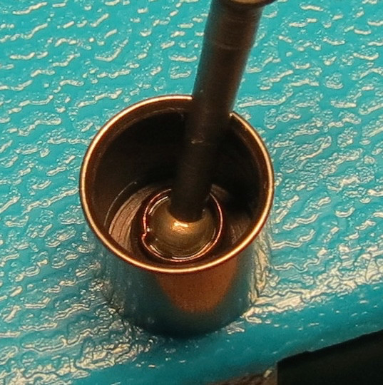
Once one start to have a closer look, the accuracy in machining is not very impressive. Here is a badly made fitting of the conrod as an example, I'm surprised it isn't simply falling out :
Variations in total length: ±0.115 mm
Variations in piston length: ±0.05 mm
This means that one can easily have and SPI difference of more than 0.2mm (!) between two different engines or after a piston change.

(this about 1/127 inch)
Here are two images showing just how much the differences in SPI can be dependent on the piston used:
(in the images I have only swapped out the pistons, everything else is the same)


Once one start to have a closer look, the accuracy in machining is not very impressive. Here is a badly made fitting of the conrod as an example, I'm surprised it isn't simply falling out :


Surfer_kris- Diamond Member

- Posts : 1912
Join date : 2010-11-20
Location : Sweden
 Re: PeeWee, differences in SPI?
Wow.. that's a bad socket joint! Do you have the reset-tool? Maybe you could take the curse off a little? I've never seen that in my pistons. It's just not characteristic of Cox quality. Inspection at the factory should have caught that. As we know; quality in general, diminished with the brands' demise.
Last edited by roddie on Thu Oct 27, 2016 3:07 pm; edited 1 time in total (Reason for editing : grammar)
 Re: PeeWee, differences in SPI?
This may be heretical observation: But I always scoffed at the notion that the manufacturing was held to millionth of an inch tolerances....considering, in my mind, the tools of the 50s, the use of war surplus materials...and a inherent knowledge of typical tooling wear
Later I had an Aha moment when I read that the Cox assy factory had dozens of well trained ladies... they would have entire barrels full of each component and they picked and choose individual parts to have a "just right" FEEL fit--- that was occasionally QC checked on and Air Micrometer Gage... I still have no idea how one works.... I personally think Millionth of an inch tolerances were more a marketing strategy that any notion of every part machining....but not a pure LIE considering they measured a fitted assy after the fact
Now this only relates to the nice complementary fit of any size piston in any sized bore... I doubt they took any steps to determine what the SPI range was
I know that IF there had been some single total piston length/height specification (instead of a range), the scrap would be unacceptable just from tooling wear and machining inaccuracies
I know that the serious Racing and FF guys bought case lots of these engines and used their own personal formula of part fit for creating repeatable and very high strung screamers.... by mixing and matching (sometime massaging) the parts

fredvon4- Top Poster


Posts : 4012
Join date : 2011-08-26
Age : 69
Location : Lampasas Texas
 Re: PeeWee, differences in SPI?
The tolerances were a heck of a lot better than the typical +- .005 inch.
With honing +- .00001 inch is pretty easy. Yes it is knowledge of tooling and wear as well as having a process that is "well controlled"
I never doubted the ability of Cox to manufacture to +- .000001 (decimal point, 5 zeros, then a 1) The practicality of it however...
Phil
With honing +- .00001 inch is pretty easy. Yes it is knowledge of tooling and wear as well as having a process that is "well controlled"
I never doubted the ability of Cox to manufacture to +- .000001 (decimal point, 5 zeros, then a 1) The practicality of it however...
Phil

pkrankow- Top Poster

- Posts : 3025
Join date : 2012-10-02
Location : Ohio
 Re: PeeWee, differences in SPI?
Hi Kris, are you planing on starting a .020 powered project?

1/2A Nut- Top Poster

- Posts : 3537
Join date : 2013-10-20
Age : 61
Location : Brad in Texas
 Re: PeeWee, differences in SPI?
I have too many projects going on and not enough time...
The PeeWee is a promising diesel conversion, and I would just like to have a muffler and an RC carb on it too. Small demands Hence the need for no, or very little. SPI.
A fully agree on the high "accuracy" coming for matching of parts rather than a true machining accuracy.
The PeeWee is a promising diesel conversion, and I would just like to have a muffler and an RC carb on it too. Small demands
A fully agree on the high "accuracy" coming for matching of parts rather than a true machining accuracy.

Surfer_kris- Diamond Member

- Posts : 1912
Join date : 2010-11-20
Location : Sweden
 Re: PeeWee, differences in SPI?
pkrankow wrote:The tolerances were a heck of a lot better than the typical +- .005 inch.
With honing +- .00001 inch is pretty easy. Yes it is knowledge of tooling and wear as well as having a process that is "well controlled"
I never doubted the ability of Cox to manufacture to +- .000001 (decimal point, 5 zeros, then a 1) The practicality of it however...
Phil
I'm sure that Cox had unique machining processes for repeatable accuracy, sustained over the duration of a parts-run. Tool-wear can be monitored before tolerances are effected. I'd never heard of an air-gap micrometer before reading this thread, but if they were made.. L.M. Cox probably had them!
The Tee Dee .010 is enough of a testament of Cox's ability to apply micro fine-machining to production-runs.
 Re: PeeWee, differences in SPI?
You may recall my effort to find a low idle solution with the Pee Wee.
Removing the tank and exposing the intake stem allowed the use of a
small G Mark .03 carb. Can recommend this solution for carb / muffler
Pee Weezie


1/2A Nut- Top Poster

- Posts : 3537
Join date : 2013-10-20
Age : 61
Location : Brad in Texas
 Re: PeeWee, differences in SPI?
Been there done that. 
I've used both a exhaust throttle and and a G-mark throttle (a .061 one with reduced bore) on a free-flight helicopter backplate etc. I wasn't too impressed with the running though, it did throttle but the engine would quit rather suddenly and I couldn't get a reliable running.
On diesel it runs much better so I'm hoping that with reduced SPI it will also run better with an RC carb and muffler. With a diesel it is quite easy to just add shim under the cylinder to remove SPI and simply compensate with the adjustable compression. The DDD heads are a bit useless though, so I will instead try to make my own, starting from a blown out plug (or maybe just modify the DDD head with a better counter piston). We'll see, it just another slow project for the winter time...

Surfer_kris- Diamond Member

- Posts : 1912
Join date : 2010-11-20
Location : Sweden
 Re: PeeWee, differences in SPI?
roddie wrote:Wow.. that's a bad socket joint! Do you have the reset-tool? Maybe you could take the curse off a little? I've never seen that in my pistons. It's just not characteristic of Cox quality. Inspection at the factory should have caught that. As we know; quality in general, diminished with the brands' demise.
Yes, it the worst piston I've seen, so far, but I think by now I have seen some really big errors in almost any part, I guess some of them just slipped through the quality control.
I have a reset tool and I'm pretty sure it is possible to fix it, but it is a lesson to learn with new engines from the box or bubble wrap. One really needs to go though them before the first run, and not take anything for granted...

Surfer_kris- Diamond Member

- Posts : 1912
Join date : 2010-11-20
Location : Sweden
 Ace throttle?
Kris, Have you thought about trying an Ace "type" throttle on a Pee Wee? I don't know the size/diameter of a Pee Wee backplates' air-intake though. I assume that it's smaller than the Bees' which is .062" (1.59mm) but I could be wrong.
In any case.. there's a metering-hole there.. and a tapered plunger could be made for it. Maybe you could use a sewing-pin/needle. The venturi being on-center with the engine-mounts, makes drilling a guide-hole through the firewall easy to do. One consideration is that a linkage will need to be behind the firewall where the fuel-tank generally is. Some people don't like the idea of removing the screen from the backplate for the fear of reed-fouling.. but you could still place a thin strip of filter-media across the bottom air-intake affixing it with rubber-bands. Maybe you have a backplate with a broken mount to sacrifice for testing?
Muffler use was recommended in Aces' kit for the Bee engines.
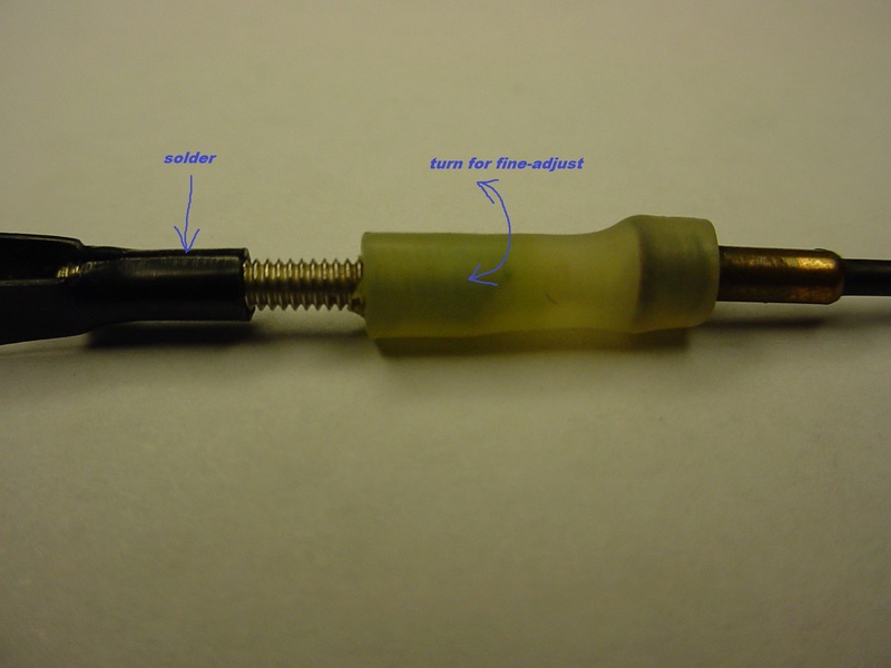
Here's an example of a servo-link that provides for some fine-adjustment by turning the silicone-sleeve in/out.


 Re: PeeWee, differences in SPI?
Yes, I will try the "Ace" type too. I have an old Super Tiger needle that fits nicely inside a backplate without a screen.

Surfer_kris- Diamond Member

- Posts : 1912
Join date : 2010-11-20
Location : Sweden
 Re: PeeWee, differences in SPI?
Cox engines are the result of exemplary American mass production techniques but tolerances of 1/millionth of an inch and mass production don't go hand in hand.
When machining a part a one off cut doesn't work! When making "one off" parts, as you close in to the required diameter, lots of things come into play most of which are dependent upon the material being machined and the tools being used.
It may be contrary to popular belief but the point of a tool bit needs to penetrate the surface of the material a certain amount before a cut can be made. This depends upon the material, the tool, the speed of the cut and the speed of movement along the material.
Imagine paring wood with a chisel - no matter how sharp the chisel - you still need a certain depth of cut to take of a sliver of wood.
Fine fits are achieved by sanding and with metal - grinding the individual part or honing two parts together. Honing is a laborious process.
I also find it difficult to contemplate the necessity for 1/millionth of an inch in a model engine. The tightness of fit is controlled by amount of interference; the allowance (planned difference from nominal size). Formulas exist [2] to compute allowance that will result in various strengths of fit such as loose fit, light interference fit, and interference fit. The value of the allowance depends on which material is being used, how big the parts are, and what degree of tightness is desired. Such values have already been worked out in the past for many standard applications, and they are available to engineers in the form of tables, obviating the need for re-derivation.
Without going into detail - there are acceptable tolerances in construction of moving parts.
As an example, a 10 mm (0.394 in) shaft made of 303 stainless steel will form a tight fit with allowance of 3–10 µm (0.0001–0.0003 in). A slip fit can be formed when the bore diameter is 12–20 µm (0.0005–0.0008 in) wider than the rod; or, if the rod is made 12–20 µm under the given bore diameter. Without going into detail - there are acceptable tolerances in construction of moving parts.
Here we are looking at ten thousands of an inch.
Piston to liner fit needs a few ten thousands of an inch to facilitate honing but the dissimilar metals do not become true unless careful running in has taken place and heating and cooling has had its way with the metals.
Cox cylinders (049 and below) are a relatively soft steel while the pistons are heat treated to harden them.
However the crown still remains relatively soft. The topside and bottom side of the crown are copper coated so that the heat treatment doesn't harden or brittle the ball socket.
All these processes render working to one millionth of an inch on the difficult side.
The variation in SPI has a number or contributory factors.
The height of the piston
The formation of the socket in the piston
The piston rod itself
The position and size of the exhaust slots in relation to the crankshaft
The final throw produced by the crankshaft
The crankshaft bore in the crankcase
The seating of the cylinder in the crankcase
It goes on ...............
Every engine will be unique on final assembly. Small errors will either increase or decrease the SPI and some will cancel each other out.
We have to accept that the Cox engines were mass produced for the lowest cost imaginable at the time and they swept away the competition. It is not surprising that there are differences.
Quality control seemed to be touch and feel piston fit to match piston and cylinder and a compression test.
Look at picture 12 here
http://www.mh-aerotools.de/airfoils/cox_album.htm
While you are there - the machinery at the time was "state of the art".

ian1954- Diamond Member

- Posts : 2688
Join date : 2011-11-16
Age : 70
Location : England
 Re: PeeWee, differences in SPI?
Surfer_kris wrote:Yes, I will try the "Ace" type too. I have an old Super Tiger needle that fits nicely inside a backplate without a screen.
Do you know off-hand, the diameter of the air-hole? I don't have any Pee Wee's to check.
I was going to mention trying an engine-needle. The taper-length can influence function. Too long; and you may need an offset bellcrank in the linkage to lengthen the effective servo-arm throw to metering-range ratio. Too short; and you lose resolution in the metering-range. It's a simple design.. but does need a good linkage. The firewalls' guide-hole should be long (deep) enough to provide straight-linear travel with a minimum of side-play to center the needle with the venturi.
A simple bench-mount can be made from 7mm plywood. After locating/drilling the four engine-mount holes.. use a straight-edge to draw an "X" connecting them. This establishes the guide-hole position. Small alloy tubing would work well for a needle (plunger) extension. Find a size that the needles' stub-end will fit into and solder it in. Match a drill-size to that tubings' O.D. and drill the plywood's guide-hole through, with a drill-press. Clean-out any small woodchips. This gives you a simple quick hand-operated throttle.
It's questionable whether this type of throttle will work as well on a Pee Wee.. let-alone a diesel-conversion, but definitely worth a try. Especially if you don't have to out-source any materials.
Some other thoughts.. In my experience with the Bee; I've found that weighting the crank seems to help with low rpm operation by flywheel-action. Heavier props can provide this, bigger props can provide this.. and/or installing a small precision steel fender-washer with the prop. No internal engine-mods.. just old stock Babe Bees.. but run mostly using a homemade muffler.. and on 25% nitro Sig fuel.
It's trial and error finding a balance-point that loads the compression-stroke for sustained firing at low (lowest) rpm.
Where you'll be running compression-ignition; I'm not sure if you'll need a muffler. Ace recommended a muffler to retain heat to the glowplug at lower rpms. If diesel runs hotter.. (IDK) you may not want a muffler installed.
Hope you find this info useful. I always write too much.
 Re: PeeWee, differences in SPI?
More info on my successful solution here:
https://www.coxengineforum.com/t9540p25-nano-td-010-130-mph-video-race-plane

My modified dissected fuel tank is not where Kris has been, the G-Mark .03 humming bird carb is much smaller I own 2 and
2 G-Mark 1cc engines. I used 30% nitro odds are he used less. I can recommend this mod to anyone with a small enough
carb for a nitro setup with the stock reed. I flared out the stem just at the carb per posted pic. Stock 4.5x2 competition
gray prop helps obtain a lower idle. The stem was shorter in the end having the carb up close to the back plate.
In the long run I like using the .020 throttle sleeves works just fine much less effort to set up, but does not tick over as
slow as this modified Pee Wee having the slowest idle I have ever heard from one. Shame there is only one cox muffler
type for the .020 cylinder it can be tapped for a pressure line which is a plus. A 4cyl .020 would be a big treat.
Some may recall the Tarno carb and back plate sold for the .049 reed engines:

Tarno Carburetor ½AR
Produced by Benjamin Tarnofsky circa 1978
The same R/C carburetor was available to be mounted on the rear induction reed valve engines. Here the complete
tank/ back plate assembly was replaced by a metal housing very similar to the very early back plates as used e.g.
in the “Shinn” aircraft model. This part contained the original reed valve with its retainer ring and provided a threaded
stub to attach the carburetor. The whole assembly was either held together by screws reaching through the firewall
or by completing the set with an additional sheet metal engine mount.

https://www.coxengineforum.com/t9540p25-nano-td-010-130-mph-video-race-plane

My modified dissected fuel tank is not where Kris has been, the G-Mark .03 humming bird carb is much smaller I own 2 and
2 G-Mark 1cc engines. I used 30% nitro odds are he used less. I can recommend this mod to anyone with a small enough
carb for a nitro setup with the stock reed. I flared out the stem just at the carb per posted pic. Stock 4.5x2 competition
gray prop helps obtain a lower idle. The stem was shorter in the end having the carb up close to the back plate.
In the long run I like using the .020 throttle sleeves works just fine much less effort to set up, but does not tick over as
slow as this modified Pee Wee having the slowest idle I have ever heard from one. Shame there is only one cox muffler
type for the .020 cylinder it can be tapped for a pressure line which is a plus. A 4cyl .020 would be a big treat.

Some may recall the Tarno carb and back plate sold for the .049 reed engines:

Tarno Carburetor ½AR
Produced by Benjamin Tarnofsky circa 1978
The same R/C carburetor was available to be mounted on the rear induction reed valve engines. Here the complete
tank/ back plate assembly was replaced by a metal housing very similar to the very early back plates as used e.g.
in the “Shinn” aircraft model. This part contained the original reed valve with its retainer ring and provided a threaded
stub to attach the carburetor. The whole assembly was either held together by screws reaching through the firewall
or by completing the set with an additional sheet metal engine mount.


1/2A Nut- Top Poster

- Posts : 3537
Join date : 2013-10-20
Age : 61
Location : Brad in Texas
 Re: PeeWee, differences in SPI?
I have a lot of options to try out. I've done that before on glo but didn't take notes on the SPI diferences between different engines, and that could be one reason for rather nonlogical results. That combined with low nitro fuel and possibly old glow plugs may well have to many uncontrolled parameters.
Once I tried it on diesel though things were much more promissing and the engine ran very well. A reliable running on useful sport props, i.e. a 6x3 prop spinnng at around 10000rpm, suited my plane (a J3 cub) very well. My goal is to improve the head construction and to add a throttle. I think an intake throttle is a safer option on diesel engines, so I will try with that first.
Here is a suitable needle (an old Super Tigre needle) for an Ace style throttle that I would like to try out on diesel:

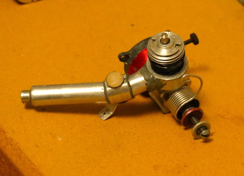
Here are also the two options that I've tried on glow in the past. The exhaust throttle worked quite well actually while the carb might have been affected by the very large SPI which that particular engine "happened" to have.

Once I tried it on diesel though things were much more promissing and the engine ran very well. A reliable running on useful sport props, i.e. a 6x3 prop spinnng at around 10000rpm, suited my plane (a J3 cub) very well. My goal is to improve the head construction and to add a throttle. I think an intake throttle is a safer option on diesel engines, so I will try with that first.
Here is a suitable needle (an old Super Tigre needle) for an Ace style throttle that I would like to try out on diesel:

Here are also the two options that I've tried on glow in the past. The exhaust throttle worked quite well actually while the carb might have been affected by the very large SPI which that particular engine "happened" to have.


Surfer_kris- Diamond Member

- Posts : 1912
Join date : 2010-11-20
Location : Sweden
 Re: PeeWee, differences in SPI?
Looks like the thread go some what off track >> I hope you will report back with the final runs on the diesel to what works out ,, Ian what was MAS-Production in 1958+ i was at a Honda engine plant a few years ago and 125 an hr. for most engines was a nom. and this was just assemblie , although they did clean the blocks of mold ridges but didn't make them if i remember correct . There were over 100 people to do this including boxing . 


getback- Top Poster


Posts : 10441
Join date : 2013-01-18
Age : 67
Location : julian , NC
 By the end of this post will be a total off topic hi-jack
Ian
I am personally NOT a machinist but had to supervise that skill set during my Army aviation career. Thus I was obligated to learn process control and many of the common engineering principles. I got pretty good at book learning
From my exploration of the Cox Mfg history. And as a side note, MY dad's command of an Army Ammunition Factory in MN. I know a lot about the concepts you posted above
I know that today we have very specialized equipment, and processes, to actually gage 1 millionth of an inch and even smaller....down to atom level...But no matter how adept Cox Co was, in 1957~59, with in house tool making, I highly doubt... the (in my mind) QC, tooling changes, and material selection was actually capable to assure .000001 tolerances in all components
Much Much later I started acquiring a lot of these VERY WELL MADE engines and they are truly good precision machines, but in my experience, a LOT of variability between parts
A little bit about my Dad's job, commanding a Ammunition plane in Minnesota... they made 5.56 ammo for the M-16 and it was a re-purposed Shot cartridge facility of Federal Cartridge---A civilian company conscripted to produce war stockage (at a huge profit)
As a Jr High kid, (14~16 YO) there were occasions and events for me to accompany my dad to his work. He was a natural teacher so during the walk around to many areas of the factory, he would describe the machines and what they were doing/and why
I know this experience was what made me a much better aircraft mechanic supervisor and Quality Control technician because I had a early schooling on the importance of QC and more to the point...WHY
Machinist errors
Materiel (inconsistency) errors
Cutting Tooling wear
Basic Tooling inaccuracies...wobble/alignment/chatter/Hell, even the density and strength of the flooring and associated vibration induced errors
My dad's plant was spitting out 2.3 MILLION 5.56 cartridges a month to support the Viet Nam war
I bet we have only a few Gun aficionados here who understand, well, the need for tight tolerances in that particular weapon and it's ammo...
Total cartridge length
Total neck length
Diameter of neck
Diameter of base cartridge
Primer charge
Powder charge
Weight of Bullet
Concentricity of Bullet
Diameter of Bullet
Length of Bullet
Interference fit of primer cup
The hijack that probaly should morph to a Off Topic or RedNeck thread
Many many gun nuts prefer the Soviet AK 47...not knowing why
But always refer to it's ability to shoot ANY CRAP ammo all the time with zero misfires
Compared to a M16 wit a inherent need for cleanliness and PRECISION Ammo
Opinion.... FAILING to acknowledge the AK 47 can indeed spray a LOT of questionable Ammo...but never seem to hit the target...While a M-16, with good ammo, is very very accurate out to 460 meters and (I can still do it) fit an entire 20 round clip in a 3 inch circle at that range.... I defy any shooter,, of any skill level, to use an AK 47 for precision work...even with match grade ammo
BUT Cox Spi was simply a way to eek out more power--- and the min and max are STILL not defined because it all depends entirely on the Fuel and compression
CEF is king of the forums!!!

fredvon4- Top Poster


Posts : 4012
Join date : 2011-08-26
Age : 69
Location : Lampasas Texas
 Ace-style needle/plunger
Surfer_kris wrote: My goal is to improve the head construction and to add a throttle. I think an intake throttle is a safer option on diesel engines, so I will try with that first.
Here is a suitable needle (an old Super Tigre needle) for an Ace style throttle that I would like to try out on diesel:
I like that ST needle set-up. Is the thread-diameter anywhere near that of the 2-56 threaded-rod used with clevises? That would greatly simplify a servo-link. Did you (or will you) glue the needle into the tube? If you could install a 2-56 threaded stub in the other end.. it would be ideal.
I'd like to try that approach.. except I'm short on orphaned/broken needles.
I'm very curious as to how you plan to proceed with a diesel head.
 Similar topics
» Davis Diesel Conversion for PeeWee and Davis Diesel Head for PeeWee
» COX Peewee 020 hop-ups
» Where to buy Cylinder and piston 020 pee wee
» Guillows Cessna build advice needed
» cox peewee .020
» COX Peewee 020 hop-ups
» Where to buy Cylinder and piston 020 pee wee
» Guillows Cessna build advice needed
» cox peewee .020
Page 1 of 1
Permissions in this forum:
You cannot reply to topics in this forum

 Rules
Rules


