Log in
Search
Latest topics
» Roger Harris revisitedby rsv1cox Today at 3:38 pm
» My N-1R build log
by GallopingGhostler Today at 3:04 pm
» Tee Dee .020 combat model
by 1/2A Nut Today at 2:43 pm
» Chocolate chip cookie dough.........
by roddie Today at 1:13 pm
» Purchased the last of any bult engines from Ken Enya
by sosam117 Today at 11:32 am
» Free Flight Radio Assist
by rdw777 Today at 9:24 am
» My latest doodle...
by batjac Yesterday at 9:47 pm
» Funny what you find when you go looking
by rsv1cox Wed Nov 20, 2024 3:21 pm
» Landing-gear tips
by 1975 control line guy Wed Nov 20, 2024 8:17 am
» Cox NaBOO - Just in time for Halloween
by rsv1cox Tue Nov 19, 2024 6:35 pm
» Canada Post strike - We are still shipping :)
by Cox International Tue Nov 19, 2024 12:01 pm
» Duende V model from RC Model magazine 1983.
by getback Tue Nov 19, 2024 6:08 am
Cox Engine of The Month
Roddie-Rigger.. a 2005 original design
Page 2 of 3
Page 2 of 3 •  1, 2, 3
 Re: Roddie-Rigger.. a 2005 original design
Rigger is looking good Roddie…. Yes, Lots of steps to think thru on a project like that, So many different little “sub” projects to make the whole….. Important to keep them in
order …
…
order

rdw777- Diamond Member


Posts : 1718
Join date : 2021-03-11
Location : West Texas
 Re: Roddie-Rigger.. a 2005 original design
rdw777 wrote:Rigger is looking good Roddie…. Yes, Lots of steps to think thru on a project like that, So many different little “sub” projects to make the whole….. Important to keep them in
order…
Thanks Robert! Yes indeed... It's been difficult to concentrate on the drive assemblies.. because of the carb options. There could be three different "lengths" at the drive-plate.. between running a straight horseshoe carb., a "choke-tube".. or a 5cc bowl/bypass.. IE "Babe Bee". I tried to work-out a best "all-around" engine mount this afternoon.. and feel like I might have fried my brain.


It's a "rigid" assembly.. so the plan is; to keep the drive-angle as shallow as possible. I made a bulkhead for that.

.. I'd need (regardless) two additional bulkheads aft; between the engine-coupling.. and the transom.... to support the stuffing-tube and share the load with the engine-mount for when the elec.-starter/belt is applied. Those mounts will need to be firm and strong. I'll be joining a 6mm PVC bulkhead to 3/16" Ultraboard (polystyrene-faced foam-board) I'm thinking some type of silicone-based sealant.. but it should be able to resist glow-fuel/wastes.
I plan to use one of my mufflers to direct exhaust-wastes through a simple/serviceable oil-sump.. and out-through the transom with reduced waste-oil content.
I'd been wanting to do a test of my prospective drive, using a Dremel-tool to provide the input RPM's.

The blocks have .159" thru-holes to accept the 5/32" (.156") stuffing-tube. That's how it'll be in the rigger.
 Re: Roddie-Rigger.. a 2005 original design
My flywheel/coupling assembly.. weighs .8oz.


The "Rod-Wrench" seems to work quite well for torquing the flywheel assy. to the engine's drive-plate. The acrylic end-bells add "mass" and make belt-starting easier. Shaft-connect/disconnect happens at the coupling; making belt-replacement easier.
The 2mm brass couplers that I bought had cheap 1.5mm grub-screws.. and several were oversize on the 2mm measurement. I drill one side for 5-40 machine-screw threads.. but the other end needs to be 2mm snug for my prop-shaft.
 Re: Roddie-Rigger.. a 2005 original design
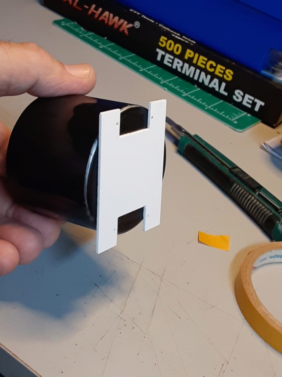
I saved some small PVC and birch "plates" about the size of credit-cards.. that were "scrap-pieces" from my last job running the CNC router at the speaker company. The stock thicknesses vary between .055" to .062" (1.4mm to 1.6mm).

The inside width of the "tub" is 3.0" so I set up my chop-saw with a stop-block/fence to cut that width to make the bulkhead(s) that will support the drive-shaft's stuffing-tube. I'll be doubling-up the panels for each bulkhead.. to make their thickness around 3mm.


I'll be cutting the bulkhead heights short enough so as to lay a panel over/across them.. to serve as a servo-mounting plate.

The inside width of the "tub" is 3.0" so I set up my chop-saw with a stop-block/fence to cut that width to make the bulkhead(s) that will support the drive-shaft's stuffing-tube. I'll be doubling-up the panels for each bulkhead.. to make their thickness around 3mm.


I'll be cutting the bulkhead heights short enough so as to lay a panel over/across them.. to serve as a servo-mounting plate.
 firewall bulkhead
The engine will tilt slightly down from a slightly elevated mounting.. in order to provide clearance for the starting-belt (O-ring).. and to position the propeller in the proximity of a "surface-drive" as it exits the transom.
To facilitate engine maintenance; I chose to glue the 5-40 nuts captive to the PVC firewall. Removal of the engine will be via a ball-end socket wrench to remove the four 5-40 cap-screws. I'll be using Testors "red-tube" cement for polystyrene and PVC throughout this build.


I glued the transom in-place tonight.


I wanted to test-mount the sponsons.. but I couldn't find any 1/4" (.014" wall) AL. tubing for the two boom-supports. I only needed two 3" length pieces. They get glued "captive" into the sides, up front. I could have sworn I had more 1/4" Al. tubing... Some of the other "tubs" (hulls) have the supports.. but not the one I chose to work with for this build.
See below; 1/4" Alum. tube boom-supports that receive the 7/32" Alum. boom-tubes.

That won't hold-up work on the model though.. I'm trying to advance in a way that seems methodical.
To facilitate engine maintenance; I chose to glue the 5-40 nuts captive to the PVC firewall. Removal of the engine will be via a ball-end socket wrench to remove the four 5-40 cap-screws. I'll be using Testors "red-tube" cement for polystyrene and PVC throughout this build.


I glued the transom in-place tonight.


I wanted to test-mount the sponsons.. but I couldn't find any 1/4" (.014" wall) AL. tubing for the two boom-supports. I only needed two 3" length pieces. They get glued "captive" into the sides, up front. I could have sworn I had more 1/4" Al. tubing...
See below; 1/4" Alum. tube boom-supports that receive the 7/32" Alum. boom-tubes.

That won't hold-up work on the model though.. I'm trying to advance in a way that seems methodical.
 Re: Roddie-Rigger.. a 2005 original design
The 12" length of 1/4" AL. tubing came yesterday.. allowing me to cut a pair of 3" length boom-tubes for the tub that I've been working on. I'll get two pair out of the 12" length.


I developed a respiratory allergy to cyanoacrylate (super-glue) years ago. Recently I thought about using some foam ear-plugs in my "nostrils"


 to prevent breathing vapors when the glue "kicks"...

Three hours later........ I feel fine and would recommend this to any of you who've had respiratory issues with modelling chemicals/paints etc. With "me".. it's the super-glue. I put packages of the foam plugs with the glues.. and "brightly-marked" to make sure I use them when working indoors where there's less ventilation.
I'd been itching to do a "mock-up" of this rigger.... because I know in my head; how it's going to look.. and I wanted y'all to get a glimpse... so here's a few pics.


The Rx/batt. and fuel tank will be forward of the engine.. placing the majority of weight over the sponson's step. Servo(s) will be aft-engine.. and I'm looking at a single-channel (rudder-only) system to start with. If the craft scoots-along pretty well... then we'll see about adding a throttle.


I developed a respiratory allergy to cyanoacrylate (super-glue) years ago. Recently I thought about using some foam ear-plugs in my "nostrils"

Three hours later........ I feel fine and would recommend this to any of you who've had respiratory issues with modelling chemicals/paints etc. With "me".. it's the super-glue. I put packages of the foam plugs with the glues.. and "brightly-marked" to make sure I use them when working indoors where there's less ventilation.
I'd been itching to do a "mock-up" of this rigger.... because I know in my head; how it's going to look.. and I wanted y'all to get a glimpse... so here's a few pics.


The Rx/batt. and fuel tank will be forward of the engine.. placing the majority of weight over the sponson's step. Servo(s) will be aft-engine.. and I'm looking at a single-channel (rudder-only) system to start with. If the craft scoots-along pretty well... then we'll see about adding a throttle.
 Re: Roddie-Rigger.. a 2005 original design
 Following along roddie , starting to look Slick ! I like the way you utilize the stuff you have on hand keeping the cost down and helps when your creating .

getback- Top Poster


Posts : 10441
Join date : 2013-01-18
Age : 67
Location : julian , NC
 Re: Roddie-Rigger.. a 2005 original design
getback wrote:Following along roddie , starting to look Slick ! I like the way you utilize the stuff you have on hand keeping the cost down and helps when your creating .


Thanks brother! It's starting to come together.
 Re: Roddie-Rigger.. a 2005 original design
Neat, clean build Roddie, Love the colors….. Two of my favorites together…. Very visible at a distance too 


rdw777- Diamond Member


Posts : 1718
Join date : 2021-03-11
Location : West Texas
 Re: Roddie-Rigger.. a 2005 original design
rdw777 wrote:Neat, clean build Roddie, Love the colors….. Two of my favorites together…. Very visible at a distance too
Hi Robert, Thank you.. I need to reexamine the rudder setup. The mount should be ok.. but the length of the blade is excessive. I also don't like the way I mounted the water pick-up tube to the rudder.
I'm going to cut at least 3/4" off the rudder-blade. I don't think it should run much deeper than the prop.

 Re: Roddie-Rigger.. a 2005 original design
Looking awesome Roddie , can’t wait to see that bad boy run 

akjgardner- Diamond Member


Posts : 1601
Join date : 2014-12-28
Age : 65
Location : Greensberg Indiana
 Re: Roddie-Rigger.. a 2005 original design
akjgardner wrote:Looking awesome Roddie , can’t wait to see that bad boy run
Joe!! Thanks man! Me too... I haven't done anything to it in several days though..
 Re: Roddie-Rigger.. a 2005 original design
So.. after a 2 week hiatus.. I finally did a little work on my rigger yesterday. The floor-plates got glued-in first..

Then I needed to fit the whole drive in place to align the bulkheads which support the stuffing-tube.. and assure clearance to R & R the O-ring/belt.


It's a one-shot deal.. because the servo(s) will mount between those two bulkheads. There will be a PVC plate that bridges across the top of them.


That servo-plate isn't glued-in yet.. because I'll need to make the cut-outs. It's there temporarily to hold the two bulkheads down and in position while the glue sets.
This morning...

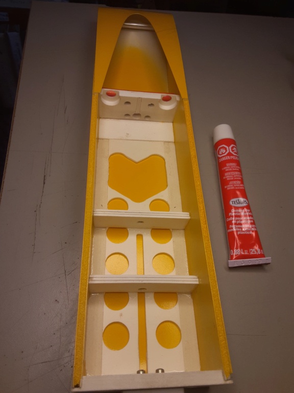
The Testors "red-tube" cement melted the thin .030" styrene a little.. .. but not too bad.


The brass stuffing-tube will be removed and "roughed-up" with sandpaper before being reinstalled and permanently glued-in.

Then I needed to fit the whole drive in place to align the bulkheads which support the stuffing-tube.. and assure clearance to R & R the O-ring/belt.


It's a one-shot deal.. because the servo(s) will mount between those two bulkheads. There will be a PVC plate that bridges across the top of them.


That servo-plate isn't glued-in yet.. because I'll need to make the cut-outs. It's there temporarily to hold the two bulkheads down and in position while the glue sets.
This morning...


The Testors "red-tube" cement melted the thin .030" styrene a little..


The brass stuffing-tube will be removed and "roughed-up" with sandpaper before being reinstalled and permanently glued-in.
 Rigger-tools
I made another tool after removing the engine from its mount.. which is now glued-in permanently. I had a 3/32" ball-end hex-key which I knew I'd need.. but nonetheless; access is tight on the bottom two screws.
Shown below with my custom "L-wrench" that I made for the shaft-coupling; I cut a short straight-length from one of my cheapie hex-keys after I test-fit some "Ace" EZ nylon fuel-tubing.. which is a super-tight fit. About a 3" length gives me a flexible-shaft to work with.


I use these plastic "take-out" containers w/lids to keep things organized between phases.

Shown below with my custom "L-wrench" that I made for the shaft-coupling; I cut a short straight-length from one of my cheapie hex-keys after I test-fit some "Ace" EZ nylon fuel-tubing.. which is a super-tight fit. About a 3" length gives me a flexible-shaft to work with.


I use these plastic "take-out" containers w/lids to keep things organized between phases.

 Re: Roddie-Rigger.. a 2005 original design
Yea HI !! Did you cut the rudder off yet ? Looks like its coming together pretty good , I have no Idea about some off the stuff ur talking about with the different parts of the boat , but enjoying the adventure ! 

getback- Top Poster


Posts : 10441
Join date : 2013-01-18
Age : 67
Location : julian , NC
 Re: Roddie-Rigger.. a 2005 original design
Nice roddie - as usual following.

rsv1cox- Top Poster


Posts : 11248
Join date : 2014-08-18
Location : West Virginia
 Re: Roddie-Rigger.. a 2005 original design
getback wrote:Yea HI !! Did you cut the rudder off yet ? Looks like its coming together pretty good , I have no Idea about some off the stuff ur talking about with the different parts of the boat , but enjoying the adventure !
Hey Bro, Nope.. but I'm fixin' to do that today.. along with fab'ing the servo-tray. I may be using a razor knife.. so..
Don't concern yourself with understanding the different parts of my boat. It has an engine, a rudder and a propeller.. just like an airplane. That's the way I'm trying to look at it when I start overthinking the design. My biggest fear with it; is that I don't finish and run it. That keeps me glued..
 Re: Roddie-Rigger.. a 2005 original design
rsv1cox wrote:Nice roddie - as usual following.
Thanks Robert.
 Re: Roddie-Rigger.. a 2005 original design
There's very little room for a radio-box in this model. I want to place the receiver, battery and fuel-cell "forward" of the engine.. to get the CG in the ball-park.
This photo makes it look like there's a lot of room..

but it's deceiving..

The fuel-cell will be just forward of the engine.. so I'm thinking that a balloon-tank will be the way to go. There's a boom-tube right there though.. The "choke-tube" works really well for pulling fuel into the venturi.. so I do have options. Maybe an "inverted wedge" (control-line stunt) would be simpler?

 Food for thought..
This photo makes it look like there's a lot of room..

but it's deceiving..

The fuel-cell will be just forward of the engine.. so I'm thinking that a balloon-tank will be the way to go. There's a boom-tube right there though.. The "choke-tube" works really well for pulling fuel into the venturi.. so I do have options. Maybe an "inverted wedge" (control-line stunt) would be simpler?


 Food for thought..
 Re: Roddie-Rigger.. a 2005 original design
Balloon tanks give very consistent runs Roddie…. Lots of advantages IMO …. Takes changing air volumes out of the equation, Conforms to the space well, Choose the fuel capacity you want, …. And fun to make!!

rdw777- Diamond Member


Posts : 1718
Join date : 2021-03-11
Location : West Texas
 Re: Roddie-Rigger.. a 2005 original design
rdw777 wrote:Balloon tanks give very consistent runs Roddie…. Lots of advantages IMO …. Takes changing air volumes out of the equation, Conforms to the space well, Choose the fuel capacity you want, …. And fun to make!!
I agree Robert.. and it looks like that's what I'll try.. at least initially. I'd really like to "free-run" the boat.. balanced and ballasted at its ready-to-run weight.. but without any radio equipment installed. This might save me some grief later on.
 Re: Roddie-Rigger.. a 2005 original design
Gluing-in the stuffing-tube (the drive-shaft spins inside of this component) required the re-installation of the engine in order to provide for proper alignment.. and the drive-shaft needed to be inserted into the drive-coupling on the engine.
Reinstalling the engine gave me a chance to test the tool that I made to help access the two "hard-to-reach" screws on the bottom of the engine-mount. It was working pretty well.. but tough to get a grip on. I knew that I could improve the tool. I had an old "jewelers-type" slotted screw-driver with a broken blade that fit perfectly tight into the other end of the Ace nylon tube.

That little screw-driver sat broken amongst others in its plastic case for decades.. and now has a new purpose in life.


This made installing those screws a LOT easier. It still requires the ball-end (3/32" hex) driver to snug the screws tight.. but that only required about one turn.
I made split-sleeves of silicone tubing to fit around the stuffing tube.. and up-against the two bulkheads to keep the glue from dripping-out of the over-size holes required to achieve the initial alignment of the bulkheads with the engine-coupling and the exit-point in the bottom of the transom.. (backside of hull).


The hull was suspended and hung; bow facing up.. to allow the glue to flow around the tube and down into the surrounding holes.


Reinstalling the engine gave me a chance to test the tool that I made to help access the two "hard-to-reach" screws on the bottom of the engine-mount. It was working pretty well.. but tough to get a grip on. I knew that I could improve the tool. I had an old "jewelers-type" slotted screw-driver with a broken blade that fit perfectly tight into the other end of the Ace nylon tube.

That little screw-driver sat broken amongst others in its plastic case for decades.. and now has a new purpose in life.


This made installing those screws a LOT easier. It still requires the ball-end (3/32" hex) driver to snug the screws tight.. but that only required about one turn.
I made split-sleeves of silicone tubing to fit around the stuffing tube.. and up-against the two bulkheads to keep the glue from dripping-out of the over-size holes required to achieve the initial alignment of the bulkheads with the engine-coupling and the exit-point in the bottom of the transom.. (backside of hull).


The hull was suspended and hung; bow facing up.. to allow the glue to flow around the tube and down into the surrounding holes.


 Re: Roddie-Rigger.. a 2005 original design
I realized that I had to move the rudder/mount off-center.. to be able to service the propeller. A prop-change requires removal of the shaft on my drive-design.. and the rudder being on-center was directly in the way. I didn't need to move the mount much.. just enough to clear the prop's "hub". The prop's blade will then auger-around the rudder-blade by slightly rotating it on removal.
I know it wasn't a great idea to set-up the drive this way.. with an unconventional propeller-mounting.. but what can I say; it's the way I roll.
I'd been putting this off.. and thought about using a different rudder.. but I decided today to stick with the one I sourced for this build.. besides; I'd already cut it shorter..


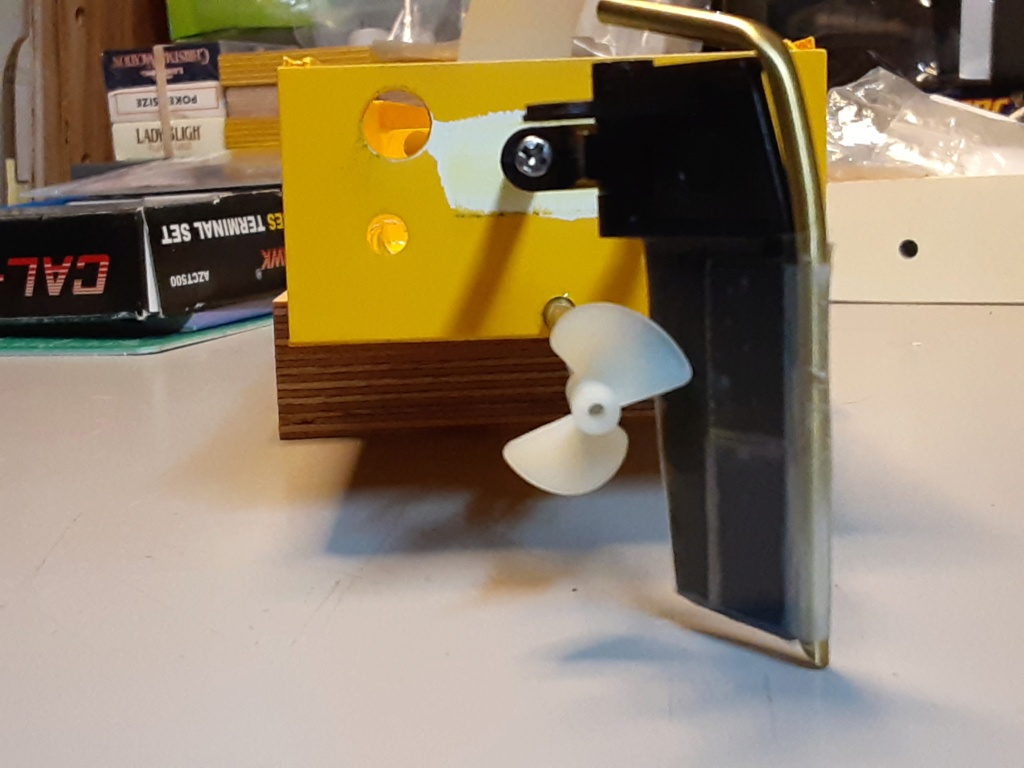
I "shortened-up" the mount and put a support block on the inside of the transom.

I gave the servo-tray some attention.. by gluing a pair of beams underneath to accept the servo-screws. The tray itself will then mount to the bulkheads using screws.

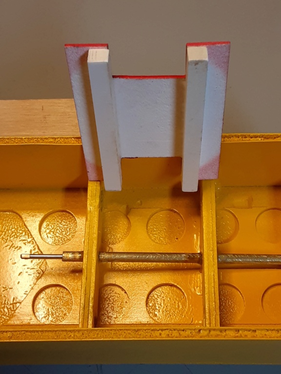


I know it wasn't a great idea to set-up the drive this way.. with an unconventional propeller-mounting.. but what can I say; it's the way I roll.
I'd been putting this off.. and thought about using a different rudder.. but I decided today to stick with the one I sourced for this build.. besides; I'd already cut it shorter..


I "shortened-up" the mount and put a support block on the inside of the transom.

I gave the servo-tray some attention.. by gluing a pair of beams underneath to accept the servo-screws. The tray itself will then mount to the bulkheads using screws.


Page 2 of 3 •  1, 2, 3
 Similar topics
» Choke Tube "stuff"...
» New P-38 profile scratch build log
» Another proposed design by Roddie
» Roddie's P-51's
» a cheap sport muffler
» New P-38 profile scratch build log
» Another proposed design by Roddie
» Roddie's P-51's
» a cheap sport muffler
Page 2 of 3
Permissions in this forum:
You cannot reply to topics in this forum

 Rules
Rules

