Log in
Search
Latest topics
» Cox films/videos...by Coxfledgling Today at 4:46 am
» Purchased the last of any bult engines from Ken Enya
by Coxfledgling Today at 4:18 am
» My N-1R build log
by roddie Today at 12:32 am
» Happy 77th birthday Andrew!
by akjgardner Today at 12:27 am
» TEE DEE Having issues
by TD ABUSER Yesterday at 9:43 pm
» Landing-gear tips
by roddie Yesterday at 6:17 pm
» Roger Harris revisited
by TD ABUSER Yesterday at 2:13 pm
» Tee Dee .020 combat model
by Ken Cook Yesterday at 1:41 pm
» Retail price mark-up.. how much is enough?
by Ken Cook Yesterday at 1:37 pm
» My latest doodle...
by roddie Yesterday at 10:43 am
» Chocolate chip cookie dough.........
by roddie Fri Nov 22, 2024 1:13 pm
» Free Flight Radio Assist
by rdw777 Fri Nov 22, 2024 9:24 am
Cox Engine of The Month
VTO free flight model
Page 2 of 4
Page 2 of 4 •  1, 2, 3, 4
 Re: VTO free flight model
For the moment, I'll stick to the stunt tank: the simplest solution, slick and tested. Glad you like the canopy!
Good to see you're back Dirk,
Where should the CG be on a delta wing? I checked some RC plans of planes with delta wings and the CG there it is located a little less than half way, starting from the leading edge. Would that be a good starting point? Anyone has experience with delta winged aircraft and CG?
Lieven

OVERLORD- Diamond Member

- Posts : 1807
Join date : 2013-03-19
Age : 58
Location : Normandy, France
 Re: VTO free flight model
On this model the CofG is trial and error. I pulled this from some build instructions.
FLYING: The model is not a super glider and it's safe to say that it will take a super-thermal for it to fly out-of-sight—so it's an ideal sport model. Don't try trimming for glide first—try for VTO power flights. Change the center of gravity location, by adding weight to the nose or tail, until the model flies vertically under power and glides in for a steep landing. If the model makes like a bomb when the engine stops, add weight to the tail. If it tries looping or winding around, add weight to the nose.
http://www.svensktmodellflyg.se/users/5466/VTO.pdf

ian1954- Diamond Member

- Posts : 2688
Join date : 2011-11-16
Age : 70
Location : England
 Re: VTO free flight model
I have a book somewhere that describes how to geometrically determine then CoG position on a delta wing. I'll see if I can find it somewhere... There's a lot of delta wing rc models on outerzone, maybe those can give you some guidelines too.

KariFS- Diamond Member

- Posts : 2044
Join date : 2014-10-10
Age : 53
 Re: VTO free flight model
Thanks guys for your imput. I looked on the web and found this:
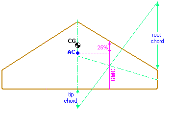
"For a delta wing the CG should be located 10% ahead of the geometrically
calculated AC point as shown above."
on this site:
http://adamone.rchomepage.com/index5.htm
It's worth a try. Kari, I'm curious to know what your book says.

"For a delta wing the CG should be located 10% ahead of the geometrically
calculated AC point as shown above."
on this site:
http://adamone.rchomepage.com/index5.htm
It's worth a try. Kari, I'm curious to know what your book says.

OVERLORD- Diamond Member

- Posts : 1807
Join date : 2013-03-19
Age : 58
Location : Normandy, France
 Re: VTO free flight model
Found it 
The method is similar (see pic) but this one does not tell you to move the CoG forward 10%. It does however show a "critical point" which is at 55% of the root chord, and you should always keep the CoG forward of that point to maintain inherent stability. I would assume that if the geometrical method puts the CoG further aft than 55% you should revise the shape of your wing.
On the left page there is a formula for the "length-width-ratio", in which
b = wing span
A = wing area.
You should try to keep the ratio between 4 and 2 to maintain stability against propeller torque. The book is about radio controlled models, printed in 1977. Your model is free flight and also otherwise rather exceptional, so maybe not all of this is applicaple. I think I'd start with the geometrical method plus 10% forward as the website says (that's a good site by the way!).
I am very curious to see how it flies
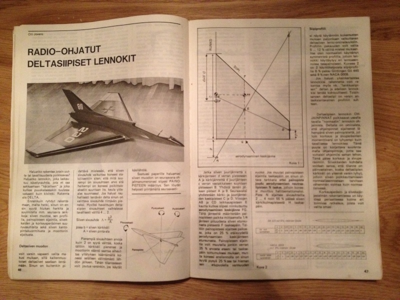
EDIT: Sorry the hosted image is a bit blurry, here's a direct link to the picture (equally blurry but maybe easier to zoom):
https://i.servimg.com/u/f86/19/04/97/47/deltas10.jpg
The method is similar (see pic) but this one does not tell you to move the CoG forward 10%. It does however show a "critical point" which is at 55% of the root chord, and you should always keep the CoG forward of that point to maintain inherent stability. I would assume that if the geometrical method puts the CoG further aft than 55% you should revise the shape of your wing.
On the left page there is a formula for the "length-width-ratio", in which
b = wing span
A = wing area.
You should try to keep the ratio between 4 and 2 to maintain stability against propeller torque. The book is about radio controlled models, printed in 1977. Your model is free flight and also otherwise rather exceptional, so maybe not all of this is applicaple. I think I'd start with the geometrical method plus 10% forward as the website says (that's a good site by the way!).
I am very curious to see how it flies

EDIT: Sorry the hosted image is a bit blurry, here's a direct link to the picture (equally blurry but maybe easier to zoom):
https://i.servimg.com/u/f86/19/04/97/47/deltas10.jpg

KariFS- Diamond Member

- Posts : 2044
Join date : 2014-10-10
Age : 53
 Re: VTO free flight model
Hey Kari, thanks!! The drawing is indeed similar to the web page drawing. Last night, I checked out other sites and found this drawing:
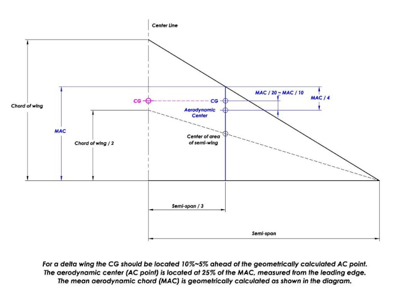
This concerns a wing ending at a point without a tip chord. The thing is that the angled sides are not leading edges but have the rib shape. Also the forward bit which is leading edge shaped is straight and at a right angle to the centre line. The shape is a bit particular. I drew some lines on the existing plan already but I will make a new drawing with dimensions.

This concerns a wing ending at a point without a tip chord. The thing is that the angled sides are not leading edges but have the rib shape. Also the forward bit which is leading edge shaped is straight and at a right angle to the centre line. The shape is a bit particular. I drew some lines on the existing plan already but I will make a new drawing with dimensions.

OVERLORD- Diamond Member

- Posts : 1807
Join date : 2013-03-19
Age : 58
Location : Normandy, France
 Re: VTO free flight model
I covered the top of the fuselage: white and red rectangles. The canopy fin is black.
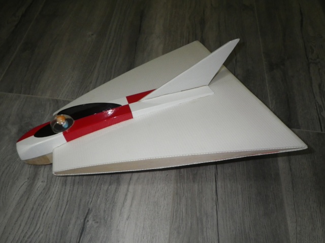
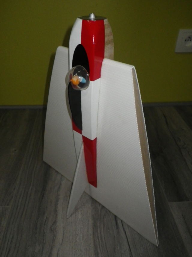

I choose Tintin for piloting the plane. I think he is the most suited person to test such an experimental and uncommon plane.
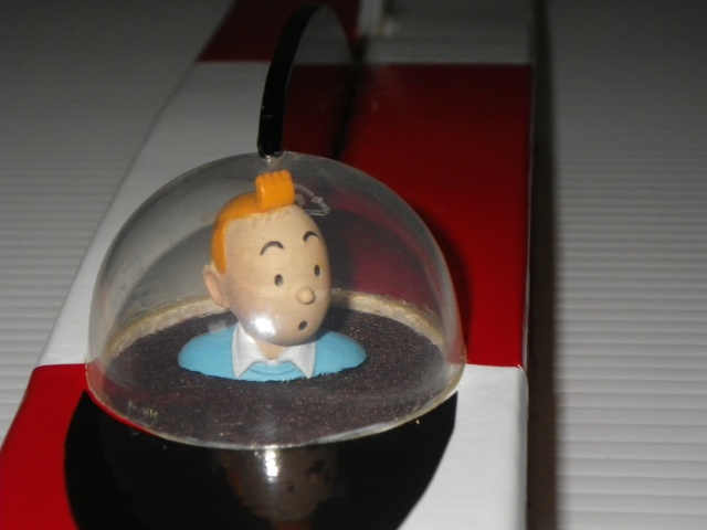
After all, he was the first man on the moon!!

The bottom half of the fuse will be painted silver (Humbrol 11).
Lieven


I choose Tintin for piloting the plane. I think he is the most suited person to test such an experimental and uncommon plane.

After all, he was the first man on the moon!!

The bottom half of the fuse will be painted silver (Humbrol 11).
Lieven
Last edited by OVERLORD on Sun Apr 24, 2016 8:20 am; edited 1 time in total

OVERLORD- Diamond Member

- Posts : 1807
Join date : 2013-03-19
Age : 58
Location : Normandy, France
 Re: VTO free flight model
Geez.. that's "wicked cool" Lieven! You never cease to amaze me with your craftsmanship and attention to detail. I read-back through the thread to refresh my brain on your dilemma with a back-end for the engine. You mentioned in option 2) that your non-vented back-plate (Golden-Bee type) has too big (2mm) of an air-intake hole to match the 5cc tank's inlet-pipe.
You probably have a late-model back-plate. Do you have any other "older" Golden Bees? Here's what I'm talking about.. shown in the photo below.
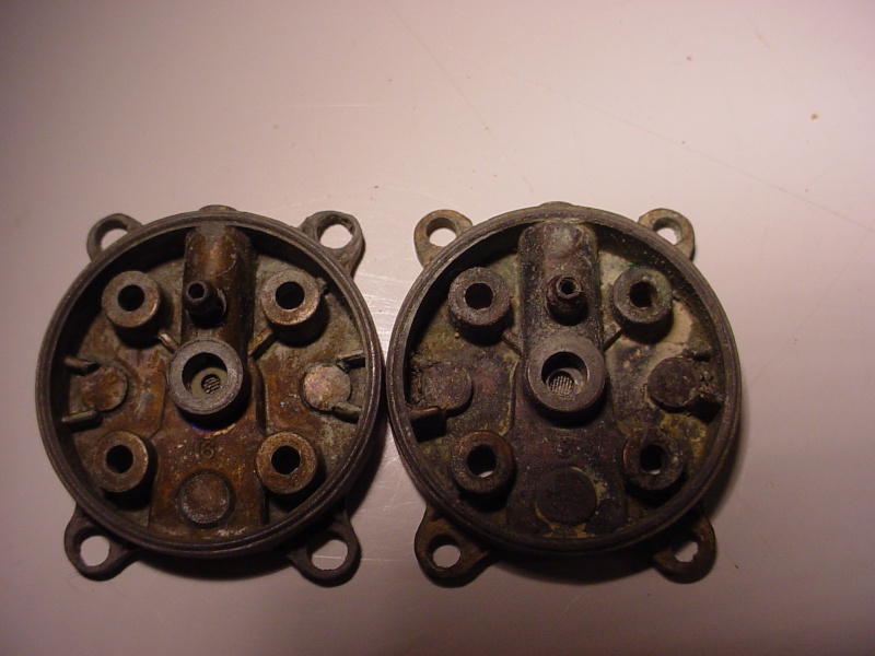
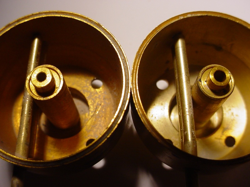
Take a close look and you'll see that the part(s) on the left side have smaller air-intake holes (same as the Babe Bee) and it will mate perfectly with the smaller 5cc tank. You could of course; plug the two vents on a Babe Bee back-plate if you don't have this early GB type. An easy way to do this might be to use a round-wooden toothpick.. and stick the point into each vent.. (apply a drop of thin CA to the point beforehand) insert tightly.. then cut-off the stub flush with a razor-saw.
Fueling/venting (siting again; your option 2) via two holes drilled in the 5cc tank. One would be a "pin-hole" (vent and the other; just big enough to insert a short (13mm) length of small silicone fuel line to achieve a compression-fit/seal. This wouldn't vibrate loose or fall out. A pin-hole vent should be small enough where you wouldn't lose much fuel due to centrifugal force. If you're concerned about that.. drill the vent-hole to accept a small copper tube with a bend in the direction of the rotation. You could actually do that with both; fill "and" vent tubes if you wanted. It's basically like "re-locating" the Babe Bee's back-plate vents to operate in a vertical orientation.
You probably have a late-model back-plate. Do you have any other "older" Golden Bees? Here's what I'm talking about.. shown in the photo below.


Take a close look and you'll see that the part(s) on the left side have smaller air-intake holes (same as the Babe Bee) and it will mate perfectly with the smaller 5cc tank. You could of course; plug the two vents on a Babe Bee back-plate if you don't have this early GB type. An easy way to do this might be to use a round-wooden toothpick.. and stick the point into each vent.. (apply a drop of thin CA to the point beforehand) insert tightly.. then cut-off the stub flush with a razor-saw.
Fueling/venting (siting again; your option 2) via two holes drilled in the 5cc tank. One would be a "pin-hole" (vent and the other; just big enough to insert a short (13mm) length of small silicone fuel line to achieve a compression-fit/seal. This wouldn't vibrate loose or fall out. A pin-hole vent should be small enough where you wouldn't lose much fuel due to centrifugal force. If you're concerned about that.. drill the vent-hole to accept a small copper tube with a bend in the direction of the rotation. You could actually do that with both; fill "and" vent tubes if you wanted. It's basically like "re-locating" the Babe Bee's back-plate vents to operate in a vertical orientation.
 Re: VTO free flight model
Regarding your stunt back-plate with the larger air-intake.. I don't see a problem running that on a 5cc tank. The "reverse" would be restrictive. You wouldn't want to run a smaller-holed back-plate on a "Black-Widow". I only noticed the difference in my two Golden Bee's recently.. and now I remember one having more power than the other. I don't remember if they had different cylinder porting or not. In the early days when I got them.. I didn't pay attention to keeping engine-parts together. As I've mentioned before; I have a theory that the later-production Golden Bees were closely on-par with Black Widows.. where they had the larger air-intake. Cox probably decided to rename and drop the Golden Bee from it's line-up.. because it wasn't really the same engine anymore.
 Re: VTO free flight model
Roddie, I haven't got such an early back plate. But to be honest, I don't like the combination of both diameters. It's creating a step in the inlet tube and that has to affect the flow of the mixture. I made a test run yesterday. The engine ran fine when horizontal but as soon as it started to revolve, it leaned out immediately and stopped. Changing the mixture to rich or lean gave the same results. After dismantling the engine, I found that the inlet tube had flipped up from the back plate. I remember wedging the tube near the backplate edge when assembling the engine but as soon as the engine started spinning, the tube probably moved. This is how I found the inlet tube:
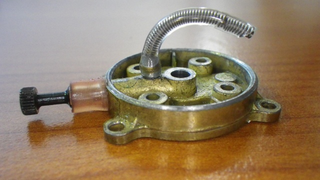
To keep the tube against the backplate, I added a bent brass pipe. I will test again this afternoon with hopefully better results.
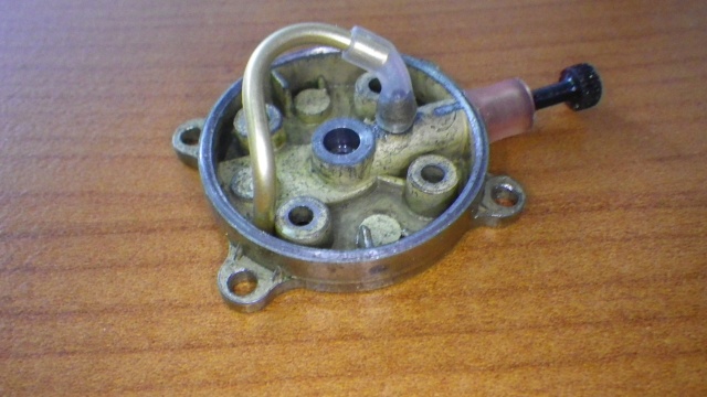

To keep the tube against the backplate, I added a bent brass pipe. I will test again this afternoon with hopefully better results.


OVERLORD- Diamond Member

- Posts : 1807
Join date : 2013-03-19
Age : 58
Location : Normandy, France
 Re: VTO free flight model
The brass pipe wasn't any better. the engine ran only 20 seconds or so while spinning around. The plane shakes a lot. I found out that the stunt tank is no good for such applications for the following reasons:
- when spinning,fuel squirts out of the filling and vent pipes
- the big distance (compared to a Bee tank or horseshoe backplate) between the cylinder and the pivot enhances the shakiing motion of the plane.
- the tank is too big to keep the fuel pick up tube in position.
I opened up the engine and made a shorter pick up tube wedged in a way as per the plans of the KAMAN free flight heli.
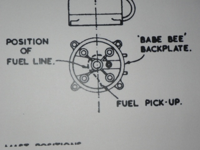
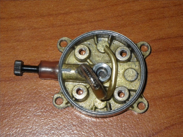

I used a Bee tank to keep the pick up tube well seated and drilled 2 holes near the crank case for filling and venting. What I said about a "step" in the inlet tube when combining a BW backplate and a standard Bee tank is nonsense. I thought it would form 1 straight inlet tube when mounted, but there is clearly a bigger chamber where the fuel nozzle is located.
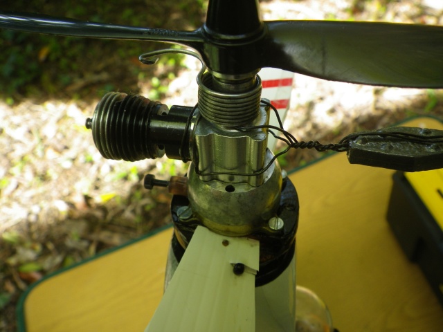
I added a lead weight which eliminated the shaking for a great part and added some more pitch to the bottom LH prop. I made that one with coroplast blades. When testing, I obtained the same results: the engine stops when spinning. And what questions me the most, as soon as the engine starts to spin, there is no more thrust or puill on the plane. If I'd let it go, it would just fall on the ground.
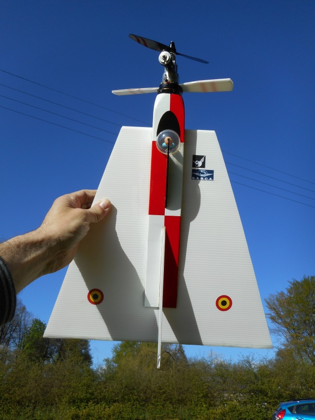
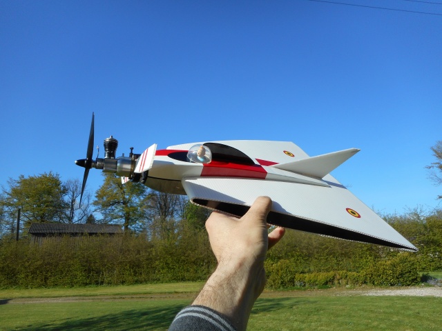
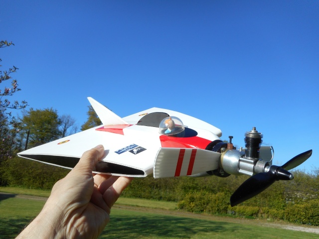
I realized I haven't posted any pictures of the finished plane. Here you go:
- when spinning,fuel squirts out of the filling and vent pipes
- the big distance (compared to a Bee tank or horseshoe backplate) between the cylinder and the pivot enhances the shakiing motion of the plane.
- the tank is too big to keep the fuel pick up tube in position.
I opened up the engine and made a shorter pick up tube wedged in a way as per the plans of the KAMAN free flight heli.


I used a Bee tank to keep the pick up tube well seated and drilled 2 holes near the crank case for filling and venting. What I said about a "step" in the inlet tube when combining a BW backplate and a standard Bee tank is nonsense. I thought it would form 1 straight inlet tube when mounted, but there is clearly a bigger chamber where the fuel nozzle is located.

I added a lead weight which eliminated the shaking for a great part and added some more pitch to the bottom LH prop. I made that one with coroplast blades. When testing, I obtained the same results: the engine stops when spinning. And what questions me the most, as soon as the engine starts to spin, there is no more thrust or puill on the plane. If I'd let it go, it would just fall on the ground.
I realized I haven't posted any pictures of the finished plane. Here you go:


OVERLORD- Diamond Member

- Posts : 1807
Join date : 2013-03-19
Age : 58
Location : Normandy, France
 Re: VTO free flight model
I now removed again the pick up tube and installed a common Cox pickup tube as for a CL plane. I still think for some reason that the engine doesn't get any fuel when spinning around. I'm changing the coroplast prop blades for 2 mini RC heli blades. I have such a machine catching dust and those blades seems to be most useful. If this engine set up still doesn't work, I have a product engine ready and I ordered a Sky Jumper tank from Bernie.
I don't know why this engine doesn't keep on running. Maybe I overlooked something?
I don't know why this engine doesn't keep on running. Maybe I overlooked something?

OVERLORD- Diamond Member

- Posts : 1807
Join date : 2013-03-19
Age : 58
Location : Normandy, France
 Re: VTO free flight model
Forgot to modify the thread title; done

OVERLORD- Diamond Member

- Posts : 1807
Join date : 2013-03-19
Age : 58
Location : Normandy, France
 Re: VTO free flight model
Just a thought: The engine might not be able to suck the fuel against the (much argued) centrifugal force. There might be a way to arrange the pipe so that the centrifugal force would actually help to feed the engine...
OR you could just leave the fuel pickup out completely, as the engine sits on its backside, I mean on its backplate
No pickup pipe would of course mean that if the model turns horizontal in flight the engine might stop earlier than it would *with* a pickup.
I am sure you will figure it out eventually
EDIT: That is a VERY NICE looking model!
OR you could just leave the fuel pickup out completely, as the engine sits on its backside, I mean on its backplate

No pickup pipe would of course mean that if the model turns horizontal in flight the engine might stop earlier than it would *with* a pickup.
I am sure you will figure it out eventually

EDIT: That is a VERY NICE looking model!

KariFS- Diamond Member

- Posts : 2044
Join date : 2014-10-10
Age : 53
 Re: VTO free flight model
The original plan shows the vent pipe modified with an elbow and the pipe almost touching the propeller. The end of the pipe has also been cut at an angle.
I presume that the open angle will be facing the direction of rotation. Probably only need the one pipe for running - the other could be blocked off after filling.
That is a fine looking model.
I presume that the open angle will be facing the direction of rotation. Probably only need the one pipe for running - the other could be blocked off after filling.
That is a fine looking model.

ian1954- Diamond Member

- Posts : 2688
Join date : 2011-11-16
Age : 70
Location : England
 Re: VTO free flight model
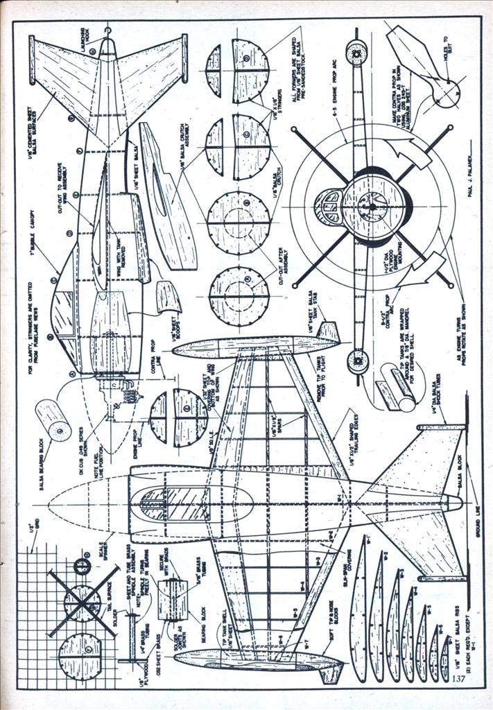
This VTO model also shows the fuel pipes forward facing but not to the same extent.


ian1954- Diamond Member

- Posts : 2688
Join date : 2011-11-16
Age : 70
Location : England
 Re: VTO free flight model
No matter what, you will need to get the fuel from wherever it is to the venturi, so routing of the fuel line won't matter. If it were me I would bring it to near the same side as the fuel nipple on the backplate, bringing it across center might be asking for trouble....sort of like having a high spot to hold bubbles. It will lean as it spins up, so you will have to set it a bit rich. On my McCutchen wing I have to set it absolutely as rich as it will possibly run and can't dally. If I get it a bit lean it works like a governer...spins up til it starts to die lean, which lets it slow down and the engine catches again. It will do this the last 10 seconds or so when the fuel gets low even on a good run.
The vent tube needs to go up and toward the crank alright. Downward might siphon fuel even if the opening is on axis. You could put an upward (forward?) loop of fuel line between the fillers with a hole in the middle for a vent...save needing to come up with a plug. With the pickup at the outer edge of the tank, this would be uniflow type venting, so the mixture should stay constant with level (but not with G load).
The stunt type fuel bowls sometimes did not have good sealing between the tank wall and the filler pipe(s). They were just a press fit. a JB weld fillet inside will fix them right up. One of the tanks I bought recently came from the supplier with JB weld already there. Can't recall if that came from our forum sponsor or a competitor.
If you can't get a good run, you might try a horseshoe backplate engine and a bladder tank. That will cover all the problems that come up with such designs...except tiny bladders are hard to come by, so you may end up needing a timer.
Edit: I don't know how I missed seeing the weight in the photo! so I took this out: "One thing that looks amiss is there is no balance weight for the cylinder. This needs to be on a forward angled arm so it rotates in plane with the cylinder for dynamic balance."

kevbo- Silver Member

- Posts : 91
Join date : 2013-03-05
 Re: VTO free flight model
Hi Lieven.. I just lost over an hour or writing.. due to a glitch. In short.. I'm wondering if your experiencing fuel-aeration from running a tank-back engine without adequate venting. I realize that you're not set up for a pressure fuel delivery. You shouldn't need one with a reed-valve engine; regardless of the orientation. Maybe a tiny "external" balloon-tank would do the trick? A "tiny" balloon encapsulated in a tube positioned 180 degrees from the engine's cylinder might help to dynamically balance the model for VTO. It only needs to run for a few seconds before transitioning to glide.
 Re: VTO free flight model
Lieven, I ran into this video on youtube, instantly thought of your project 
https://m.youtube.com/watch?v=5J6D8a3SIvg
https://m.youtube.com/watch?v=5J6D8a3SIvg

KariFS- Diamond Member

- Posts : 2044
Join date : 2014-10-10
Age : 53
 Re: VTO free flight model
Thanks for posting tha video Kari, That model flies just like the real plane.
As Kevbo said, bringing fuel to the centre on a spinning engine is a difficult task. A few days ago, I received the Sky Jumper fuel tank from Bernie. Next thing to do is to connect that tank to a product engine and mount the engine out of centre similar as on the Sky Jumper. Work and the garden keep me from a bit of modeling these days. It's not fair!!


As Kevbo said, bringing fuel to the centre on a spinning engine is a difficult task. A few days ago, I received the Sky Jumper fuel tank from Bernie. Next thing to do is to connect that tank to a product engine and mount the engine out of centre similar as on the Sky Jumper. Work and the garden keep me from a bit of modeling these days. It's not fair!!

OVERLORD- Diamond Member

- Posts : 1807
Join date : 2013-03-19
Age : 58
Location : Normandy, France
 Re: VTO free flight model
Lieven, I have a feeling that running an integral tank is causing your problems, regardless of the pick-up position or venting. As soon as the spinning starts.. the fuel will start to aerate when it gets agitated by the bosses/steps in the backplate, the four screws holding the tank together.. and the fuel pick-up itself. Your virtually sucking foam in a very short amount of time. A pressure-bladder may be the only answer to getting fuel straight to the venturi.
Then again.. this little .010 does a lot of spinning.. Maybe there's less chance of foaming with it's tank design?
https://www.youtube.com/watch?v=Q7MwFVHCRpY
Then again.. this little .010 does a lot of spinning.. Maybe there's less chance of foaming with it's tank design?

https://www.youtube.com/watch?v=Q7MwFVHCRpY
 Re: VTO free flight model
Hi Lieven, I had an idea to help balance your model. Cox International (Bernie) sells an exhaust deflector that could be mounted 180 degrees to the engine cylinder.. with a weight rigidly attached to it. Kari actually mentions on page one of this thread; using it as a fuel line bracket.

A spherical weight such as an egg-shaped fishing sinker would conform nicely to the radius of the shield.. and could be held neatly in place with heat-shrink tubing. Alternately; match the radius of the shield, to a piece of steel rod cut to a length as to balance.. and epoxy or braze it to the shield. I don't think the wired-on weight is a good idea.. and may actually cause you more problems.. like wobbling.

A spherical weight such as an egg-shaped fishing sinker would conform nicely to the radius of the shield.. and could be held neatly in place with heat-shrink tubing. Alternately; match the radius of the shield, to a piece of steel rod cut to a length as to balance.. and epoxy or braze it to the shield. I don't think the wired-on weight is a good idea.. and may actually cause you more problems.. like wobbling.
Last edited by roddie on Sun May 15, 2016 7:46 pm; edited 1 time in total (Reason for editing : Kari reference)
 Re: VTO free flight model
Roddie, Thank you for the ideas. I had a good look at the various free flight helicopter plans on Outerzone. Non of them except for the Kaman have a reed valve engine. The fuel tanks have the delivery tube at the side and running up to the engine. The Sky Copter or the Cox flying Saucer also have separate tanks. I will follow that principle. I got my TD out and a TD tank. It gives a similar configuration as the TD 010 with the rag in the video. I made already 2 blades of 0,9 mm aluminium. I started making one months ago but it's not easy while cutting and filing to keep them straight, hence my trial with coroplast blades. However, the great advantage of the alu blades is that you can change the pitch by bending the metal. As the TD is bolted on, I can use those bolts to make a counterweight from another cylinder and a u shaped plate. The steel wire was just something I came up with in a hurry. When finished, it should look a bit like this:


OVERLORD- Diamond Member

- Posts : 1807
Join date : 2013-03-19
Age : 58
Location : Normandy, France
 Re: VTO free flight model
Today, I did some tests with the new power plant. An 051 TD and TD tank. On the engine bearers, I bolted a top hat shaped aluminium bracket to which I glued a cylinder as counterweight.
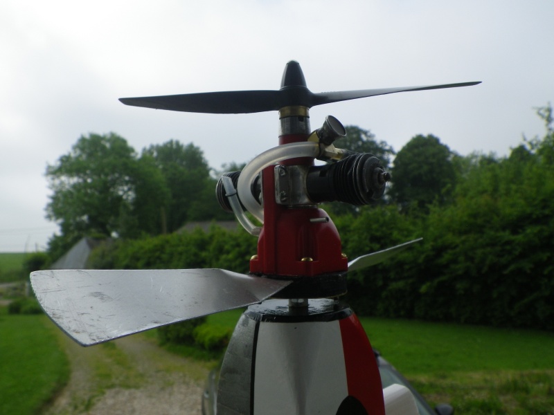
The aluminium blades are set at 30°. The engine started OK, ran good horizontally and vertically. I let the blades go and the thing started spinning. I let it go and it went up about 4 m or 12ft in the air before the engine stopped. The plane turned 180° and came back again as a brick. I did a few more tests with the same results. Each time the engine stopped but without speeding up as if it would go lean. I rerouted the fuel tube by turning the needle valve to see if that would be any better but it made no difference, at least, it wasn't any better. The inlet and overflow pipes on the tank are connected together with a silicon tube and a slit cut in the middle. After each test, I found the fuel tube still full. Why would the engine stop? Something to do with the mesh on the venturi? Cuts off air when spinning?

I also increased the pitch on the blades without any better results. The plane flew more in a curve, as an inverted parabole than straight up. I then had to stop as the soldered brass base plate for the engine mount was loose on the shaft.
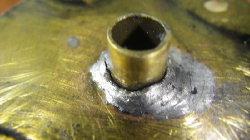
After cleaning I removed the engine. I put the fuel tubing back as it was and mounted a TD venturi without mesh. I reset the aluminium blades at 30°. I made 2 separate brass breathing pipes for the filling and overflow pipes of the fuel tank.


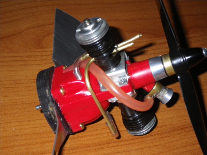
The much more performing TD and the bigger pitch of the blades made a great difference compared to the Bee engine. The results are encouraging.
Things to do:
Solder the brass plate
Fix some weight on the tail
Concentrate on how to prevent the engine from stopping.
Lieven

The aluminium blades are set at 30°. The engine started OK, ran good horizontally and vertically. I let the blades go and the thing started spinning. I let it go and it went up about 4 m or 12ft in the air before the engine stopped. The plane turned 180° and came back again as a brick. I did a few more tests with the same results. Each time the engine stopped but without speeding up as if it would go lean. I rerouted the fuel tube by turning the needle valve to see if that would be any better but it made no difference, at least, it wasn't any better. The inlet and overflow pipes on the tank are connected together with a silicon tube and a slit cut in the middle. After each test, I found the fuel tube still full. Why would the engine stop? Something to do with the mesh on the venturi? Cuts off air when spinning?

I also increased the pitch on the blades without any better results. The plane flew more in a curve, as an inverted parabole than straight up. I then had to stop as the soldered brass base plate for the engine mount was loose on the shaft.

After cleaning I removed the engine. I put the fuel tubing back as it was and mounted a TD venturi without mesh. I reset the aluminium blades at 30°. I made 2 separate brass breathing pipes for the filling and overflow pipes of the fuel tank.


The much more performing TD and the bigger pitch of the blades made a great difference compared to the Bee engine. The results are encouraging.
Things to do:
Solder the brass plate
Fix some weight on the tail
Concentrate on how to prevent the engine from stopping.
Lieven

OVERLORD- Diamond Member

- Posts : 1807
Join date : 2013-03-19
Age : 58
Location : Normandy, France
Page 2 of 4 •  1, 2, 3, 4
 Similar topics
» Charybdis-a free-flight model
» Flying wing free flight model
» Flying Sorcerer free flight model First flights !!!
» New Hobby???? Free Flight.....
» F1a free flight
» Flying wing free flight model
» Flying Sorcerer free flight model First flights !!!
» New Hobby???? Free Flight.....
» F1a free flight
Page 2 of 4
Permissions in this forum:
You cannot reply to topics in this forum

 Rules
Rules


