Log in
Search
Latest topics
» Cox films/videos...by Coxfledgling Today at 4:46 am
» Purchased the last of any bult engines from Ken Enya
by Coxfledgling Today at 4:18 am
» My N-1R build log
by roddie Today at 12:32 am
» Happy 77th birthday Andrew!
by akjgardner Today at 12:27 am
» TEE DEE Having issues
by TD ABUSER Yesterday at 9:43 pm
» Landing-gear tips
by roddie Yesterday at 6:17 pm
» Roger Harris revisited
by TD ABUSER Yesterday at 2:13 pm
» Tee Dee .020 combat model
by Ken Cook Yesterday at 1:41 pm
» Retail price mark-up.. how much is enough?
by Ken Cook Yesterday at 1:37 pm
» My latest doodle...
by roddie Yesterday at 10:43 am
» Chocolate chip cookie dough.........
by roddie Fri Nov 22, 2024 1:13 pm
» Free Flight Radio Assist
by rdw777 Fri Nov 22, 2024 9:24 am
Cox Engine of The Month
"Pusher" powered
Page 1 of 1
 "Pusher" powered
I have been curious about this more unorthodox method of moving the aircraft's prop rearward of the center of gravity. Thinking about it just now.. I came up with the theory...  that the "thrust" produced by a spinning propeller, is an element in itself.. that has fascinating properties. The "thrust" primarily.. but think about what's actually happening. We take it for granted with tractor/conventional airframes. The prop is grabbing the air that it's pitch and diameter dictate.. and forcing it rearward.. with a force governed by rpm's. This is easy to understand.. and most aero-modelers are focusing on getting the ideal prop to suit the engine on a given model.. for a given design/style of flying.
When I think about a "pusher" design.. the thrust-element is diffused into parts. The pull-push "linear" thrust-element, the gyroscopic effect produced and applied on the roll axis.. and where that force is centered; with regard to the c/g... and expanding on the linear element; the angle of thrust-offset.. for the desired trim.. These are pretty much the factors.. aren't they?
If I want to "push" a wing.. as opposed to pulling it... how will that affect a tail-plane? Could the engine be mounted near the C/G.. and a prop-shaft extension used? Would these elements considered; make for effective trimming on a c/l stunt model?
 Re: "Pusher" powered
Good questions that I could only give a wild guess at. I might poke around the "Stunt Design" and "Engineering Board" sections over at Stunthanger.com where the scientists and aerospace experts hang out and see if it's addressed.
Rusty
Rusty
_________________
Don't Panic!
...and never Ever think about how good you are at something...
while you're doing it!
My Hot Rock & Blues Playlist
...and never Ever think about how good you are at something...
while you're doing it!
My Hot Rock & Blues Playlist

RknRusty- Rest In Peace

- Posts : 10869
Join date : 2011-08-10
Age : 68
Location : South Carolina, USA
 Re: "Pusher" powered
Here is an excellent article on the issues with pusher design:
http://www.djaerotech.com/dj_askjd/dj_questions/pushtractor.html
http://www.djaerotech.com/dj_askjd/dj_questions/pushtractor.html

dirk gently- Gold Member

- Posts : 430
Join date : 2012-02-03
Age : 42
Location : Poznań
 Re: "Pusher" powered
dirk gently wrote:Here is an excellent article on the issues with pusher design:
http://www.djaerotech.com/dj_askjd/dj_questions/pushtractor.html
Very interesting read!! It seems that "propeller" efficiency suffers; in most.. if not all designs.. where the airflow forward of it is disturbed by the airframe. Lots of issues for full-scale designs. Flying wings were mentioned as being better candidates. After reading the article, I can certainly understand why there aren't a lot of pusher-designs out there.
Thanks for posting the link Dirk.
 Re: "Pusher" powered
This guy has a lot more interesting articles on his site. He actually explains stuff that you can find in any aerodynamics handbook, but actually does that in a way that let's someone with some modelling experience, but perhaps with no PhD in physics understand it.

dirk gently- Gold Member

- Posts : 430
Join date : 2012-02-03
Age : 42
Location : Poznań
 Re: "Pusher" powered
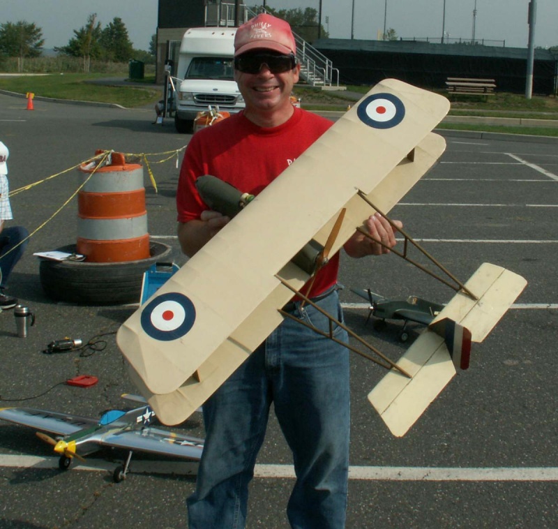
The problem with a pusher is that your engine goes rich rather than lean when entering maneuvers. This is a result of the tank being in front of the engine. Not a good thing when you need the power. My friend Dan resolved this issue when he built his scale Farman Bipe. Here's a picture I took of him when we entered a "Fun Scale" at Palisades Park, New Jersey a few years ago. Dan custom built a shaft for the LA .46 which utilized a rag joint similar to a steering column joint. The engine was in the nose with the shaft running directly through a tunnel just like a rear wheel drive car. The tank was constructed with a hull like appearance in which the shaft ran through it. It was remarkably engineered and it worked flawlessly. The plane met it's demise when the wind came over the trees where we fly at on the weekends. It pretty much splatted the plane into the ground. Ken


Ken Cook- Top Poster

- Posts : 5640
Join date : 2012-03-27
Location : pennsylvania
 Re: "Pusher" powered
That's always sad to hear about Ken. It must have sucked to see happen. I've seen that airplane before.. probably a different model.. but I remember it. I really like bipes... and "tripes" for that matter. I'm trying to visualize the tank in that Farman bipe. Was it like a "saddle" arrangement? Did the extended prop-shaft run over.. or under it? Just curious. I'm sure it was a good size tank for the .46. It looks like the engine is mounted upright with it's cylinder just forward of the wing's leading-edge? It's hard to tell from the photo. Were there any engine cooling issues?
This "rag-joint" I am curious about. Can you elaborate a little bit on the materials Dan used? I've been toying in my mind with extended-shaft drives.. where there would be at least one angle to deal with. One such drive is a "marine" application.. but the other is aircraft. The aircraft is a 1/2A "Stiletto" control-line model.
This plan references a steel universal joint.. pillow-block/bearings type set-up... but there doesn't appear to be any angular changes in the drive-line. Maybe this helps with any slight misalignment when building?

Of course.. we're talking 1/2A here.. as compared to a big .46.. but I'm just curious about what the coupling consisted of.. and whether Dan ran his shaft in a sleeve.. or whether he used a pillow-block/bearing set-up? I can't imagine trying to flip-start that .46 with those tail-booms in the way..
This "rag-joint" I am curious about. Can you elaborate a little bit on the materials Dan used? I've been toying in my mind with extended-shaft drives.. where there would be at least one angle to deal with. One such drive is a "marine" application.. but the other is aircraft. The aircraft is a 1/2A "Stiletto" control-line model.
This plan references a steel universal joint.. pillow-block/bearings type set-up... but there doesn't appear to be any angular changes in the drive-line. Maybe this helps with any slight misalignment when building?

Of course.. we're talking 1/2A here.. as compared to a big .46.. but I'm just curious about what the coupling consisted of.. and whether Dan ran his shaft in a sleeve.. or whether he used a pillow-block/bearing set-up? I can't imagine trying to flip-start that .46 with those tail-booms in the way..
 Re: "Pusher" powered
That's always sad to hear about Ken. It must have sucked to see happen. I've seen that airplane before.. probably a different model.. but I remember it. I really like bipes... and "tripes" for that matter. I'm trying to visualize the tank in that Farman bipe. Was it like a "saddle" arrangement? Did the extended prop-shaft run over.. or under it? Just curious. I'm sure it was a good size tank for the .46. It looks like the engine is mounted upright with it's cylinder just forward of the wing's leading-edge? It's hard to tell from the photo. Were there any engine cooling issues?
This "rag-joint" I am curious about. Can you elaborate a little bit on the materials Dan used? I've been toying in my mind with extended-shaft drives.. where there would be at least one angle to deal with. One such drive is a "marine" application.. but the other is aircraft. The aircraft is a 1/2A "Stiletto" control-line model.
This plan references a steel universal joint.. pillow-block/bearings type set-up... but there doesn't appear to be any angular changes in the drive-line. Maybe this helps with any slight misalignment when building?

Of course.. we're talking 1/2A here.. as compared to a big .46.. but I'm just curious about what the coupling consisted of.. and whether Dan ran his shaft in a sleeve.. or whether he used a pillow-block/bearing set-up? I can't imagine trying to flip-start that .46 with those tail-booms in the way..
This "rag-joint" I am curious about. Can you elaborate a little bit on the materials Dan used? I've been toying in my mind with extended-shaft drives.. where there would be at least one angle to deal with. One such drive is a "marine" application.. but the other is aircraft. The aircraft is a 1/2A "Stiletto" control-line model.
This plan references a steel universal joint.. pillow-block/bearings type set-up... but there doesn't appear to be any angular changes in the drive-line. Maybe this helps with any slight misalignment when building?

Of course.. we're talking 1/2A here.. as compared to a big .46.. but I'm just curious about what the coupling consisted of.. and whether Dan ran his shaft in a sleeve.. or whether he used a pillow-block/bearing set-up? I can't imagine trying to flip-start that .46 with those tail-booms in the way..
 Re: "Pusher" powered
Roddie, the shaft ran under the tank. The shaft indeed was in a pillow block with a bearing and yes cooling and also alignment was an issue to the point that it cost Dan 3 LA .46's until he got it corrected. The engine is mounted inverted and starting the 11 x 4 was certainly an issue. I would start the plane many of the times. You wouldn't really flip the prop like one would conventionally on a open nose stunter. I would grab the prop by the center section and flip it backwards with my thumb and forefinger like I was trying to snap my fingers. It would light off pretty quickly. The joint itself coming off of the engine utilized a couple he made that threaded onto the shaft with a mating flange. The shaft also had this flange and this rubberized cloth he attained was in between the flanges. This assembly was also balanced. Dan and Bob Zambelli worked on this project together. It really was a neat piece of engineering. The tank and shaft still exists and he mentioned that some day he might build another. The struts in the rear were carbon arrow shafts. The projection that you see in front of the leading edge in the picture is Snoopy. Ken

Ken Cook- Top Poster

- Posts : 5640
Join date : 2012-03-27
Location : pennsylvania
 Re: "Pusher" powered
Ken Cook wrote:Roddie, the shaft ran under the tank. The shaft indeed was in a pillow block with a bearing and yes cooling and also alignment was an issue to the point that it cost Dan 3 LA .46's until he got it corrected. The engine is mounted inverted and starting the 11 x 4 was certainly an issue. I would start the plane many of the times. You wouldn't really flip the prop like one would conventionally on a open nose stunter. I would grab the prop by the center section and flip it backwards with my thumb and forefinger like I was trying to snap my fingers. It would light off pretty quickly. The joint itself coming off of the engine utilized a couple he made that threaded onto the shaft with a mating flange. The shaft also had this flange and this rubberized cloth he attained was in between the flanges. This assembly was also balanced. Dan and Bob Zambelli worked on this project together. It really was a neat piece of engineering. The tank and shaft still exists and he mentioned that some day he might build another. The struts in the rear were carbon arrow shafts. The projection that you see in front of the leading edge in the picture is Snoopy. Ken
Thanks Ken. I'm always interested in knowing about how modelers overcome obstacles.. when building an unorthodox model.
 Similar topics
» Cox Pusher product Engine w/ Tornado Pusher Prop, spinner
» Cardboard inserts+Instruction sheets
» Thimble Drome Champion
» *Cox Engine of The Month* Submit your pictures! -April 2023-
» Cox 1948 Pusher Car
» Cardboard inserts+Instruction sheets
» Thimble Drome Champion
» *Cox Engine of The Month* Submit your pictures! -April 2023-
» Cox 1948 Pusher Car
Page 1 of 1
Permissions in this forum:
You cannot reply to topics in this forum

 Rules
Rules


