Log in
Search
Latest topics
» Retail price mark-up.. how much is enough?by gkamysz Today at 9:29 pm
» Happy 77th birthday Andrew!
by roddie Today at 9:22 pm
» Roger Harris revisited
by rsv1cox Today at 3:38 pm
» My N-1R build log
by GallopingGhostler Today at 3:04 pm
» Tee Dee .020 combat model
by 1/2A Nut Today at 2:43 pm
» Chocolate chip cookie dough.........
by roddie Today at 1:13 pm
» Purchased the last of any bult engines from Ken Enya
by sosam117 Today at 11:32 am
» Free Flight Radio Assist
by rdw777 Today at 9:24 am
» My latest doodle...
by batjac Yesterday at 9:47 pm
» Funny what you find when you go looking
by rsv1cox Wed Nov 20, 2024 3:21 pm
» Landing-gear tips
by 1975 control line guy Wed Nov 20, 2024 8:17 am
» Cox NaBOO - Just in time for Halloween
by rsv1cox Tue Nov 19, 2024 6:35 pm
Cox Engine of The Month
Dynomometer build (for air-screws)
Page 2 of 3
Page 2 of 3 •  1, 2, 3
 Re: Dynomometer build (for air-screws)
Surfer_kris wrote:roddie wrote: It was important for Aeromodeller Magazine to test the Tee Dee .049 in 1962.. and state it's output power (bph/watts) and maximum torque (ounce/in.) at given rpm's.. on specified fuel. How do you suppose they came up with their numbers?
Roddie
I think they ran a calibrated flywheel (with known inertia) and measured the rpm as the engine accelerates. From that you can then calculate the power and torque vs rpm.
You're probably right Kris.. If you follow my threads, you'll notice that I tend to be a "tinkerer". I enjoy experimenting with my own designs/concepts. I'm not what you'd call "well read" by any means. Sometimes I make statements based on how I think something should work.. rather than proven theory. The fact is; I enjoy "tinkering".. and sharing my experience with others.
This Dyno-build.. I feel may be helpful to me on several levels; as I also experiment with throttles and a homemade muffler for the Cox .049. The "muffler" has a large degree of adjustable flow/back-pressure; through the use of varying orifice pipes that can be changed quickly. I think that recording "static thrust" measurements with different pipes will prove interesting as opposed to running an engine with open-face exhaust. The throttle that I'm experimenting with; is not an exhaust throttle... it's a venturi-needle/plunger pioneered by "Ralph Cooney" and was marketed by "Ace RC" under their p/n 630. It works with "Bee-style" back-plates and meters fuel and air.
Surely I could just mount an engine on a block of wood and run it; taking tach measurements.. but to "me", it's far more interesting to have more information. For those who dismiss this work as a waste of time... they have a choice to ignore my efforts altogether.. or view them for entertainment value. If my sharing of information through experimentation (whether successful or not..) helps another modeler... or improves the usability of a Cox engine... then it's time well spent in my opinion.
Roddie
 Re: Dynomometer build (for air-screws)
It is a hobby so there is no wasted time, by definition. 
I was just curious regarding the purpose of this entrapment...
There is a tread on RCU (by combatpig) regarding different props and their static thrust;
1/2a thrust-o-meter
(I just realized that that thread is about ten years old, time goes fast...)
I was just curious regarding the purpose of this entrapment...
There is a tread on RCU (by combatpig) regarding different props and their static thrust;
1/2a thrust-o-meter
(I just realized that that thread is about ten years old, time goes fast...)

Surfer_kris- Diamond Member

- Posts : 1912
Join date : 2010-11-20
Location : Sweden
 Re: Dynomometer build (for air-screws)
I am following your build, experiments like this are a great part of the hobby. I'm sure your results will be usefull.

Exsanitary- Moderate Poster

- Posts : 28
Join date : 2012-02-06
Location : Palominas, Arizona
 Re: Dynomometer build (for air-screws)
ian1954 wrote:
I admire the efforts made by Roddie and am watching them closely. I will follow his progress, learn from his mistakes, copy his design, improve it and build a better one!!!
I did warn you! I have turned the motion through 90 deg, replaced the wood with plastic and metal, solved the problem of the upside down reading and fitted bearings for the swingy bit.
Still work in progress but it is now known, in honour of the inspiration provided. as the "Roddiemometer".


ian1954- Diamond Member

- Posts : 2688
Join date : 2011-11-16
Age : 70
Location : England
 Re: Dynomometer build (for air-screws)
ian1954 wrote:ian1954 wrote:
I admire the efforts made by Roddie and am watching them closely. I will follow his progress, learn from his mistakes, copy his design, improve it and build a better one!!!
I did warn you! I have turned the motion through 90 deg, replaced the wood with plastic and metal, solved the problem of the upside down reading and fitted bearings for the swingy bit.
Still work in progress but it is now known, in honour of the inspiration provided. as the "Roddiemometer".
Impressive sir!!! Are those threaded rods/fittings leftover from your printer-build?
 Re: Dynomometer build (for air-screws)
Roddie, That's a proven arrangement. Looking good!
Ian, that prop looks dangerous...
Phil
Ian, that prop looks dangerous...
Phil

pkrankow- Top Poster

- Posts : 3025
Join date : 2012-10-02
Location : Ohio
 Re: Dynomometer build (for air-screws)
The threaded rods, M8 thread, are remnants from the printer build. All the plastic stuff is newly "designed" and built. The bearings modified slightly from my balance gadget - a flat bottom added.
Trying to work on a "universal" motor mount for quick attach and detach and the associated series of prints. That will be trial and error.
As usual, with anything I do, there will be a lot of trial and error.
I use M6, M8 and M10 studding quite a lot. It is cheap and very useful for make clamps, hold downs, frames ..........easy to get in most hardware stores or builders merchants.
Metric taps an dies are quite cheap here as well.

ian1954- Diamond Member

- Posts : 2688
Join date : 2011-11-16
Age : 70
Location : England
 Re: Dynomometer build (for air-screws)
pkrankow wrote:Roddie, That's a proven arrangement. Looking good!
Ian, that prop looks dangerous...
Phil
When I have sorted the motor mount - I will show you a dangerous propeller!

ian1954- Diamond Member

- Posts : 2688
Join date : 2011-11-16
Age : 70
Location : England
 Re: Dynomometer build (for air-screws)
pkrankow wrote:Roddie, That's a proven arrangement. Looking good!
Ian, that prop looks dangerous...
Phil
C'mon Phil... what's so dangerous about a prop with a serrated edge?
Roddie
 Re: Dynomometer build (for air-screws)
The one from Ian can have a second use, just turn the engine by 90° and you can measure the engine torque too. 
Take an rpm reading and you have the BHP...
Here is some useful info regarding torque measurements and different props; http://modelenginenews.org/techniques/testing.html
Dynos; http://www.clcombat.info/dyno.html

Take an rpm reading and you have the BHP...
Here is some useful info regarding torque measurements and different props; http://modelenginenews.org/techniques/testing.html
Dynos; http://www.clcombat.info/dyno.html


Surfer_kris- Diamond Member

- Posts : 1912
Join date : 2010-11-20
Location : Sweden
 Re: Dynomometer build (for air-screws)
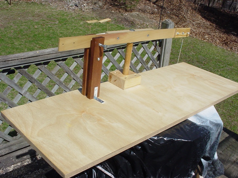
I'm not much further along with this.. but today the weather was nice.. and I needed to fuel-proof it. It was too much to do inside this past Winter. Plus.. I wanted to resurrect the thread, because Ian was working on his own design.. and I'm curious if he's made progress.
To recap; this design uses a horizontal "beam" that pivots on a pin in the center, with engine/motor mounted on the left side facing forward.. and a digital hanging scale on the right side for measuring the amount of "pull" on the beam in ounces/grams.
Remaining steps for functionality are; fabricating an adjustable mount for a fuel tank, mounts for the scale and a tach.. and mounting a power panel. Calibration will be done using a second identical scale. Scales will be mounted for calibration on opposing sides/ends of the beam.
So far I have two interchangeable mounts for running Cox .049 reed-valve engines. One is for the horseshoe back-plate and the other is for the Bee-style tank-back-plate.
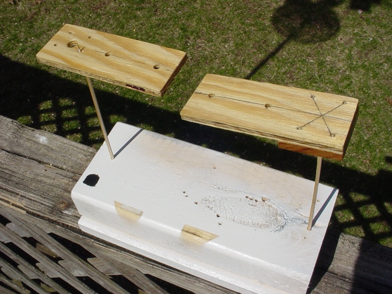


 Ian's thrust/stress meter
Another very useful function of Ian's design - when thoroughly fed up, simply rotate the engine arm out of the way. Then bang your head against the measuring thrust plate and VIOLA! An empirical reading of your frustration level!
To be scientifically precise, stress levels should be measured in beers.
To be scientifically precise, stress levels should be measured in beers.

VUgearhead- Gold Member

- Posts : 155
Join date : 2013-07-02
Age : 57
Location : Boynton Beach, FL
 Re: Dynomometer build (for air-screws)
VUgearhead wrote:Another very useful function of Ian's design - when thoroughly fed up, simply rotate the engine arm out of the way. Then bang your head against the measuring thrust plate and VIOLA! An empirical reading of your frustration level!
To be scientifically precise, stress levels should be measured in beers.
That Ian..... he thinks of everything... always trying to "one-up" me...


 Re: Dynomometer build (for air-screws)
Roddie:
Being trumped in the humor department is so sin.
SD
Being trumped in the humor department is so sin.

SD

SuperDave- Rest In Peace

- Posts : 3552
Join date : 2011-08-13
Location : Washington (state)
 Re: Dynomometer build (for air-screws)
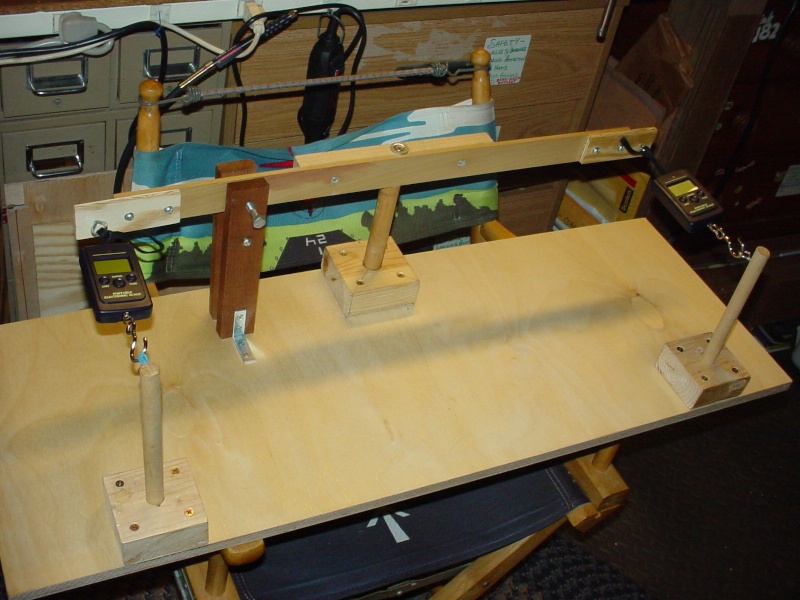
OK.. some more progress. The "beam" design has had calibration posts installed, that hold two identical scales in suspension; one being solid-mounted and the other tensioned by a spring or rubber band. This yielded a .2oz. variation from one side of the beam to the other. That's pretty close considering the variables that I cannot control. The left hand scale and post are temporary for this purpose only.
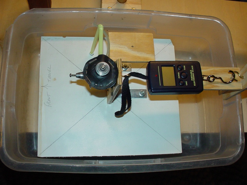
I mentioned how I felt that a "floating" fixture should be the most accurate for pulling on a scale-hook.. so I made one. The tub is just a small rectangular plastic bin with a block of 1.5" thick foam-board cut to fit with only slight side-clearance and a couple inches of linear travel in the direction of thrust/scale-hook pull. Approximately 2 liters of water floats the fixture to a height where the two scale-hook mounts are level. I made a mount for an external fuel tank, swappable to either dyno.. which is height adjustable and also swivels. My homemade muffler is shown on a .049 prod. engine here, with an exhaust extension (bendy straw) routed down through a hole in the foam float. All the other parts to both dynos are standard hdwe. items and wood pieces.. and it's just a matter of size/alignment to build either of them. All parts have been fuel-proofed and ready for testing.
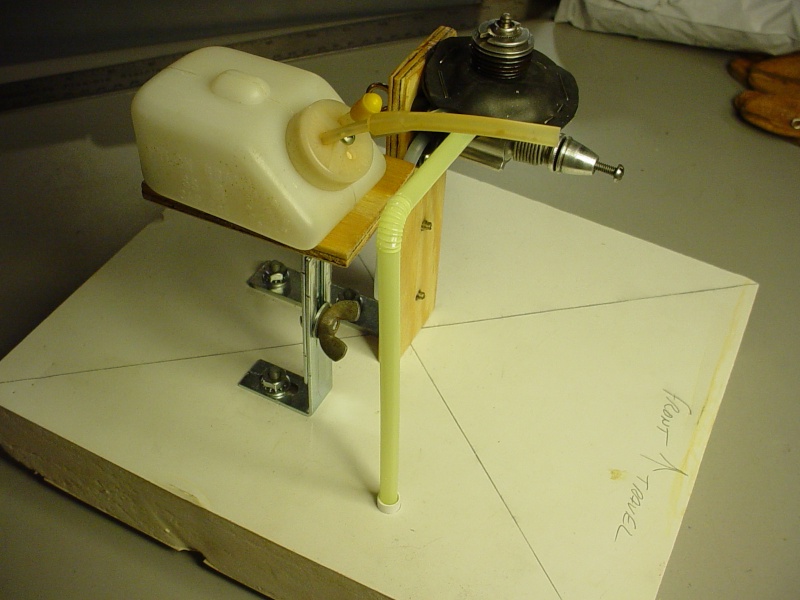

I mentioned how I felt that a "floating" fixture should be the most accurate for pulling on a scale-hook.. so I made one. The tub is just a small rectangular plastic bin with a block of 1.5" thick foam-board cut to fit with only slight side-clearance and a couple inches of linear travel in the direction of thrust/scale-hook pull. Approximately 2 liters of water floats the fixture to a height where the two scale-hook mounts are level. I made a mount for an external fuel tank, swappable to either dyno.. which is height adjustable and also swivels. My homemade muffler is shown on a .049 prod. engine here, with an exhaust extension (bendy straw) routed down through a hole in the foam float. All the other parts to both dynos are standard hdwe. items and wood pieces.. and it's just a matter of size/alignment to build either of them. All parts have been fuel-proofed and ready for testing.


 Re: Dynomometer build (for air-screws)
Try not to laugh please... this was my 1st attempt.
"3rd time's a charm"... notice how it took me a bit to realize the engine had started backwards...
Here's a 2nd try... average pull was 5 ounces @12-13K avg. rpm's with a 3-blade 5 x 3 prop on Sig Champion 25.
That uni-flow tank is one of the ones I made for my speed contest model. Capacity is 7.7cc. I think the cylinder/piston is pretty worn out by those tach #'s.. earlier tests with my muffler yielded an avg. 3 ounce pull while using x1 wide-open header-pipe with an exhaust extension running down through the floor of the float. It would barely needle into a 2-stroke. It was quiet though!
 Re: Dynomometer build (for air-screws)
Roddie, The tub's a great idea! It may not give absolute values, but it's a great way to do comparative testing for different prop/plug/shim/fuel combinations. I may have to "borrow" the idea to test some combinations in the future. At least for the next Reed Speed contest. I just ordered a couple of those scales off of Amazon to test Cox stuff. Also, I can use them later in the year to weigh my luggage for a flight we're taking.
The Borrower Mark
The Borrower Mark
batjac- Diamond Member


Posts : 2374
Join date : 2013-05-22
Age : 61
Location : Broken Arrow, OK, USA
 Re: Dynomometer build (for air-screws)
Cool Roddie, very useful!

Cribbs74- Moderator


Posts : 11907
Join date : 2011-10-24
Age : 50
Location : Tuttle, OK
 Re: Dynomometer build (for air-screws)
batjac wrote:Roddie, The tub's a great idea! It may not give absolute values, but it's a great way to do comparative testing for different prop/plug/shim/fuel combinations. I may have to "borrow" the idea to test some combinations in the future. At least for the next Reed Speed contest. I just ordered a couple of those scales off of Amazon to test Cox stuff. Also, I can use them later in the year to weigh my luggage for a flight we're taking.
The Borrower Mark
Thanks for watching/commenting Mark and Ron. The "tub" with a floating fixture offers very little resistance for a scale reading. Notice that the scale sits on a plate mounted to the tub.. and I pull the fixture back before powering-up the scale, to allow it to "zero" itself before releasing the fixture to apply tension. The small zip-seal bag over the scale keeps it clean from oil in the prop-wash.
The next step is to mount that same engine/prop/tank combo on the beam-style dyno, and run it on the same fuel, to see if I get similar avg. readings on it's scale. Technically; if the engine rpm's are the same.. I should get similar scale-readings if the beam is calibrated correctly. The beam-style dyno will have a power-panel mounted to it, a "hands-free" cradle for the tach and has a "beam-lock" so that the scale can be "zeroed" prior to applying tension. I also need to mount a variable "weight-vessel" to the scale-side of the beam, to compensate for the engine-side's weight; which might be augmented by accessories such as a throttle servo/linkage at some point and calibrated by dual opposing scales.. which mounts have already been built and tested to give very close readings without a weight-vessel. The idea is to be able to dial-in accuracy.
 Re: Dynomometer build (for air-screws)
Dude, that's a great idea. What was the scale reading at it's max?
_________________
Don't Panic!
...and never Ever think about how good you are at something...
while you're doing it!
My Hot Rock & Blues Playlist
...and never Ever think about how good you are at something...
while you're doing it!
My Hot Rock & Blues Playlist

RknRusty- Rest In Peace

- Posts : 10869
Join date : 2011-08-10
Age : 68
Location : South Carolina, USA
 Re: Dynomometer build (for air-screws)
RknRusty wrote:Dude, that's a great idea. What was the scale reading at it's max?
Hey Rusty, Thanks! With that engine; I was seeing readings of 5.1 ounces @ 13K rpm's. Let's just say that if you were able to build an airplane; weighing less than (without it's engine).. what it's planned engine is capable of pulling.. then that airplane should (in theory) have "unlimited" vertical performance. This is just one of the useful aspects of building a test fixture such as this. Sure; there are a lot of factors that influence real-world performance.. but if you know your engine will pull a certain amount of weight "static" on the test fixture where the prop is loaded to the max... it should be some indication of how the model will perform when put into an abrupt climbing maneuver.. like the start of a square loop for instance.
 Re: Dynomometer build (for air-screws)
Just saw this unit on another site and remembered this thread. It seems to me it might be easily converted for use with nitro engines maybe
http://hobbyking.com/hobbyking/store/__66623__Turnigy_Thrust_Stand.html?utm_campaign=141203.USE&utm_content=135957858&utm_medium=email&utm_source=EDM
Demo
https://www.youtube.com/watch?v=aizFyrzhbdY
Apparently price is about US$50 plus shipping. Seems a pretty cool item
http://hobbyking.com/hobbyking/store/__66623__Turnigy_Thrust_Stand.html?utm_campaign=141203.USE&utm_content=135957858&utm_medium=email&utm_source=EDM
Demo
https://www.youtube.com/watch?v=aizFyrzhbdY
Apparently price is about US$50 plus shipping. Seems a pretty cool item

Davenz13- Platinum Member

- Posts : 597
Join date : 2013-11-28
Age : 69
Location : Palmerston North, New Zealand
 Re: Dynomometer build (for air-screws)
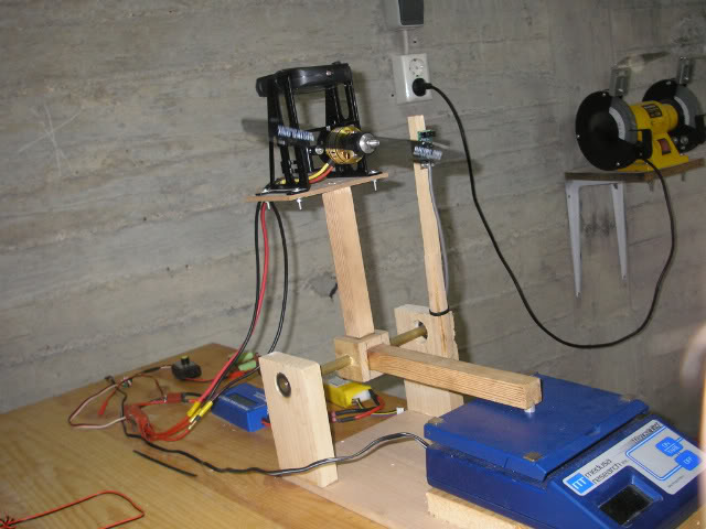
Simple DIY thrust stand using a scale...


1/2A Nut- Top Poster

- Posts : 3537
Join date : 2013-10-20
Age : 61
Location : Brad in Texas
 Re: Dynomometer build (for air-screws)
Davenz13 wrote:Just saw this unit on another site and remembered this thread. It seems to me it might be easily converted for use with nitro engines maybe
http://hobbyking.com/hobbyking/store/__66623__Turnigy_Thrust_Stand.html?utm_campaign=141203.USE&utm_content=135957858&utm_medium=email&utm_source=EDM
Demo
https://www.youtube.com/watch?v=aizFyrzhbdY
Apparently price is about US$50 plus shipping. Seems a pretty cool item
Thanks for posting Dave. That's a pretty cool product! I think there were questions as to the "usefulness" of a thrust meter, when I started this thread.. but it really makes sense to me. Watching the vid, I can see where it's very useful for electrics.. and utilizing a watt-meter to get the most efficiency out of your system with a given prop.
A Winter project is in the works to build a test-tub (not tube..
Probably just another one of my crazy notions.. Actually, plastic lawn-edging might work well for the walls.
 and if I can form the outer wall with the "finned" side in.. it may decrease turbulence.
Hey 1/2A nut.. Thanks for chiming-in. Do you have any experience using .062" flex-cable running in a 3/32" brass stuffing-tube? I have the materials.. and was wondering if it's possibly strong enough for a small Cox reed-valve .049 powered rigger that I'm building?
 Re: Dynomometer build (for air-screws)
Dumas uses 1/8in solid steel drive lines, 1in prop with 1in pitch so at .062in you are pushing it. When the flex cable winds up under load you have to make sure the raps are going the right direction to tighten as the prop loads up the line. A cut down Octura 27mm x 1.4in pitch to 24mm dia may keep the cable from breaking. 2mm wire drives can handle 70 to 100w tops you're at 1.6mm If you use a reed engine you maybe ok should be about 65w given a TD can do up to 80w.

1/2A Nut- Top Poster

- Posts : 3537
Join date : 2013-10-20
Age : 61
Location : Brad in Texas
Page 2 of 3 •  1, 2, 3
 Similar topics
» Screws For Engines
» 8 cc fuel tank screws
» Phillips Head Tank Screws
» Cox bee tank extenders
» Cox .010 tank screws
» 8 cc fuel tank screws
» Phillips Head Tank Screws
» Cox bee tank extenders
» Cox .010 tank screws
Page 2 of 3
Permissions in this forum:
You cannot reply to topics in this forum

 Rules
Rules

