Log in
Search
Latest topics
» My latest doodle...by batjac Yesterday at 10:05 pm
» Retail price mark-up.. how much is enough?
by gkamysz Yesterday at 9:29 pm
» Happy 77th birthday Andrew!
by roddie Yesterday at 9:22 pm
» Roger Harris revisited
by rsv1cox Yesterday at 3:38 pm
» My N-1R build log
by GallopingGhostler Yesterday at 3:04 pm
» Tee Dee .020 combat model
by 1/2A Nut Yesterday at 2:43 pm
» Chocolate chip cookie dough.........
by roddie Yesterday at 1:13 pm
» Purchased the last of any bult engines from Ken Enya
by sosam117 Yesterday at 11:32 am
» Free Flight Radio Assist
by rdw777 Yesterday at 9:24 am
» Funny what you find when you go looking
by rsv1cox Wed Nov 20, 2024 3:21 pm
» Landing-gear tips
by 1975 control line guy Wed Nov 20, 2024 8:17 am
» Cox NaBOO - Just in time for Halloween
by rsv1cox Tue Nov 19, 2024 6:35 pm
Cox Engine of The Month
Dynomometer build (for air-screws)
Page 1 of 3
Page 1 of 3 • 1, 2, 3 
 Dynomometer build (for air-screws)
I finally started working on this project yesterday... and got far enough along for the design to look feasible and start a thread, which will also commit me to finishing/testing it. This design is currently limited to Cox reed-valve (radial mount) .049 engines, because that's mostly what I have.
Not my original concept of a buoyant fixture, but as long as I can calibrate it, it should work. This design uses a horizontal beam with a pin/spindle through the center. The beam-travel will be limited to under 1/2" by using stops for safety.
I wanted a contained unit that wouldn't take up too much space, and be easy to set up. 1st order was safety.. and a design that would isolate an IC engine's exhaust wastes from most of the other components... The "beam" makes this possible. It mounts to a pedestal at the rear of a plywood base that is 36" wide by 13" deep (a size that I had on hand).. The beam is 24" long and has a centerline that is 7" above the base for plenty of propeller-arc clearance and has interchangeable "bolt-on" engine mounts for Bee or horseshoe-style back-plates. The beam will also have a counter-weight-box on the opposite side from the engine/motor's mounting. (behind the scale-hook)
A power-panel will be mounted front/center, powered by two 6V lantern batteries in series. I am building the mounts now, for a tach, external fuel cell and the digital hanging scale. Although this instrument doesn't measure torque.. it "will" measure pull; in ounces/grams. I bought 2 scales (they were inexpensive and measure weight in Lb./JIN/OZ/Kg) and will use both to check calibration on opposing sides of the beam, which use screw-eyes for the scale-hooks. Fuel-proofing will be all that's left to do after that... then it will be ready to test.

below-"Bee" and "horseshoe" back-plate mounts (need to re-design the horseshoe mount for needle access)

below-"Bee" mount.. on the beam.
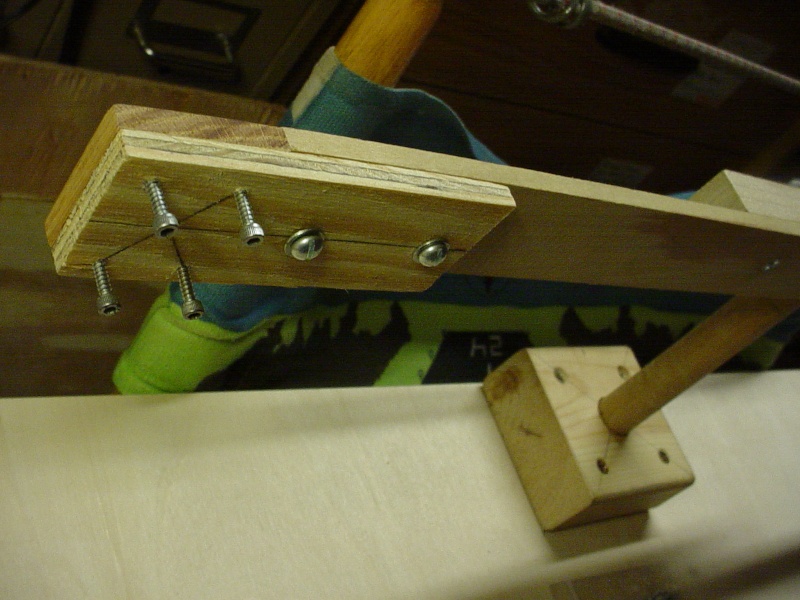


There's still some construction bugs to work out... The "horseshoe" back-plate mounts' needle access.. and the scale's read-out is inverted. ... I'll have to do a little more tweaking.
Roddie
Not my original concept of a buoyant fixture, but as long as I can calibrate it, it should work. This design uses a horizontal beam with a pin/spindle through the center. The beam-travel will be limited to under 1/2" by using stops for safety.
I wanted a contained unit that wouldn't take up too much space, and be easy to set up. 1st order was safety.. and a design that would isolate an IC engine's exhaust wastes from most of the other components... The "beam" makes this possible. It mounts to a pedestal at the rear of a plywood base that is 36" wide by 13" deep (a size that I had on hand).. The beam is 24" long and has a centerline that is 7" above the base for plenty of propeller-arc clearance and has interchangeable "bolt-on" engine mounts for Bee or horseshoe-style back-plates. The beam will also have a counter-weight-box on the opposite side from the engine/motor's mounting. (behind the scale-hook)
A power-panel will be mounted front/center, powered by two 6V lantern batteries in series. I am building the mounts now, for a tach, external fuel cell and the digital hanging scale. Although this instrument doesn't measure torque.. it "will" measure pull; in ounces/grams. I bought 2 scales (they were inexpensive and measure weight in Lb./JIN/OZ/Kg) and will use both to check calibration on opposing sides of the beam, which use screw-eyes for the scale-hooks. Fuel-proofing will be all that's left to do after that... then it will be ready to test.

below-"Bee" and "horseshoe" back-plate mounts (need to re-design the horseshoe mount for needle access)

below-"Bee" mount.. on the beam.


There's still some construction bugs to work out... The "horseshoe" back-plate mounts' needle access.. and the scale's read-out is inverted.
 ... I'll have to do a little more tweaking.
Roddie
 Re: Dynomometer build (for air-screws)
Interesting idea. I like it.

Cajun66- Silver Member

- Posts : 75
Join date : 2014-01-03
Age : 50
Location : Baton Rouge, Louisiana
 Re: Dynomometer build (for air-screws)
Cajun66 wrote:Interesting idea. I like it.
Thanks Matt, I brought this idea up previously... and it was met with some (warranted) skepticism... "Why not just hook the scale to the back of your airplane while running?"... was one comment. That would work for a particular model... but I'd rather have some controls in place, when making performance measurements... the ability to easily swap fuel cells with different blends and having a "hands-free" tach while adjusting the needle.
By using removable mounts, I can pull an engine off the test fixture quickly; by removing two wing-nuts. I'd rather know what kind of performance I have... "before" I mount an engine in a model.

 Re: Dynomometer build (for air-screws)
Good work, Roddie.
Suggestion deleted because you'll come up with a better idea.
Rusty
Suggestion deleted because you'll come up with a better idea.
Rusty
_________________
Don't Panic!
...and never Ever think about how good you are at something...
while you're doing it!
My Hot Rock & Blues Playlist
...and never Ever think about how good you are at something...
while you're doing it!
My Hot Rock & Blues Playlist

RknRusty- Rest In Peace

- Posts : 10869
Join date : 2011-08-10
Age : 68
Location : South Carolina, USA
 Re: Dynomometer build (for air-screws)
Just remember if you want consistent readings and the engines to be comparable, you have to use the same pitch and length prop for all of them. Also the distance the engine is from the center post will also affect the reading.

G.O. Stang- Gold Member

- Posts : 317
Join date : 2013-05-20
Age : 30
Location : Brenham, Tx
 Re: Dynomometer build (for air-screws)
Looks good Roddie!
Something to consider from a safety standpoint is engine surge. As in it may go on and off of peak until tuned.
If that happens it could oscillate that big arm back and forth making it dangerous to try and grab the needle and tune.
Maybe you could design a pin release that keeps things steady until you are done peaking the engine?
Just a thought, I will be watching the thread.
Ron

Cribbs74- Moderator


Posts : 11907
Join date : 2011-10-24
Age : 50
Location : Tuttle, OK
 Re: Dynomometer build (for air-screws)
Cribbs74 wrote:Looks good Roddie!
Something to consider from a safety standpoint is engine surge. As in it may go on and off of peak until tuned.
If that happens it could oscillate that big arm back and forth making it dangerous to try and grab the needle and tune.
Maybe you could design a pin release that keeps things steady until you are done peaking the engine?
Just a thought, I will be watching the thread.
Ron
You're absolutely correct Ron. You must have missed that point in my 2nd paragraph (1st post) where I mentioned that the beam will have less than 1/2" of travel by using stops for safety... because the beam only needs to tension the scale-hook to achieve a reading.
Another benefit of this device, is to map the performance of my homemade muffler's inter-changeable header-pipes... which have 12 sizes from .144" thru .204" (.22 cal. shell-casings, drilled-out in .005"/.008" increments)
I sent Rusty a muffler package to try, with a complete pipe assortment, pressure-tap and some extra un-drilled pipes to experiment with. He's going to test it on his Tee Dee soon. I'm not sure how it will affect SPI... but I suggested starting with large pipe diameters... and gradually switching to smaller ones. I'm hoping that the mufflers will also help to dial-in the models' airspeed... possibly taming a model that flies too fast for stunt. I hope he has good luck with it... I don't have any Tee Dee's to try it on.
Roddie
Roddie
 Re: Dynomometer build (for air-screws)
I see now. I did read that, but it totally went over my head. If it were me though I would want it dead solid even a small (1/2")amount of back and forth movement is enough to allow your fingers to slip and bump the prop.
Just wanted to make sure you were safe! I see you have that covered though. Sorry about that.
Ron
Just wanted to make sure you were safe! I see you have that covered though. Sorry about that.
Ron

Cribbs74- Moderator


Posts : 11907
Join date : 2011-10-24
Age : 50
Location : Tuttle, OK
 Re: Dynomometer build (for air-screws)
Cribbs74 wrote:I see now. I did read that, but it totally went over my head. If it were me though I would want it dead solid even a small (1/2")amount of back and forth movement is enough to allow your fingers to slip and bump the prop.
Just wanted to make sure you were safe! I see you have that covered though. Sorry about that.
Ron
No worries Ron! Thanks for your concern.. I appreciate you caring enough to mention a possible hazard. I also appreciate your (and anyone else's) interest in this project. It makes it worth writing about.
Thinking back... the Dyno that I built years ago.. had a pendulum that swung between 2 uprights.. and used a lock-pin. I can build a lock or "screw-clamp" into this design (as well as the safety stops) that would hold the beam tight until ready to take a reading on the scale. I'm even nutty enough to make an interlock.. to prevent juice from going to the plug unless the beam is locked!
Roddie (the nutty inventor)
 dynometer build
Very interesting project being a cabinetmaker and model builder!If you get it up and running it would be neat to see a small video of it working if possible! 


craig bernard- Gold Member

- Posts : 155
Join date : 2013-11-09
Age : 63
Location : penetanguishene,ontario canada
 Re: Dynomometer build (for air-screws)
I wonder if this precision ball bearing linear slide would make a good base for a dyno? Buttery smooth with very little friction. Mount an engine test stand to it with a pull scale on the back to measure the pull.


Jason_WI- Top Poster


Posts : 3123
Join date : 2011-10-09
Age : 49
Location : Neenah, WI
 Re: Dynomometer build (for air-screws)
Hey, Roddie, not to worry, I plan to put your muffler to the test. Just haven't had any flying weather around here lately. I'll be using my two Tee Dee powered planes even more now since my Norvel powered Streak is out of commission.
Rusty
Rusty
_________________
Don't Panic!
...and never Ever think about how good you are at something...
while you're doing it!
My Hot Rock & Blues Playlist
...and never Ever think about how good you are at something...
while you're doing it!
My Hot Rock & Blues Playlist

RknRusty- Rest In Peace

- Posts : 10869
Join date : 2011-08-10
Age : 68
Location : South Carolina, USA
 Re: Dynomometer build (for air-screws)
Jason_WI wrote:I wonder if this precision ball bearing linear slide would make a good base for a dyno? Buttery smooth with very little friction. Mount an engine test stand to it with a pull scale on the back to measure the pull.
Hey Jason! That slide would work nice I'm sure. I've thought a bit about coming up with a minimal-friction carriage... and had originally planned to "float one" in a shallow pan of water (like a cake pan... or something a little larger) Then I got to thinking... when the linkage to the scale-hook is taught, the carriage is no longer in motion and any axle, wheel-set or roller should work equally well. The difference in the "floating" carriage is; it's basically "weightless" and would be the most accurate... but we're starting to "split hairs" here... probably talking micro-grams difference with something this small.
As long as the dyno/fixture is accurate in calibration, it should produce fairly accurate thrust readings... and any deviations in a given engines' performance, will definitely be accurate... because a baseline has been established.
Roddie
 Re: Dynomometer build (for air-screws)
I like it Roddie, I think/hope it should work great, i had designed one very similar, the reasoning behind the offset lever is the engine will pull harder on the scale and should show a greater differential, due to the higher numbers from one engine to another, also this set-up puts the exhaust away from the scale.
 Re: Dynomometer build (for air-screws)
I think I understand how it is meant to work, but I don't understand the purpose.
Is it to measure different engines or props?
Is it to measure different engines or props?

Surfer_kris- Diamond Member

- Posts : 1912
Join date : 2010-11-20
Location : Sweden
 Re: Dynomometer build (for air-screws)
The static thrust doesn't say very much though. Props can be off in terms of their pitch for instance, thereby giving you very good static thrust but only a small thrust once in the air with some airspeed forward.
Engines can be tested/compared by using the same prop. The rpm will give you a relative measure of their power. Even then the static rpm is not always a good measure, some engines will unload more in the air, and thereby have a more useful power...
All in all, it is simplest and morefun to fly airplanes with different engines and props in order to come up with the best combination...

Surfer_kris- Diamond Member

- Posts : 1912
Join date : 2010-11-20
Location : Sweden
 Re: Dynomometer build (for air-screws)
Surfer_kris wrote:I think I understand how it is meant to work, but I don't understand the purpose.
Is it to measure different engines or props?
Hi Kris, Yes.. like Mark Boesen replied. To explain in more detail; a Dyno can help you to tune your engine for optimal performance, by showing you how much weight it's able to pull. One engine may pull 4 ounces when using a certain fuel/prop/cylinder type/glow-head type/number of head gaskets... etc. Many variables... Changing any one of them will affect performance that will be measurable using a dyno.
A Dyno isn't going to appeal to everybody and it's certainly not something that's needed... but most of us bench-run our engines/motors at some point.. and it's wise to do this before putting it on/in your model. Just like having a tach; it's interesting to see the #'s.... combine a tach with a scale that measures ounces of "pull"... and you have an instrument for accurately documenting performance variations which is important to some people.
This Dyno design is a trial.. and could be built a number of ways. Safety should be a major concern, as with anything else. The engine/motor mounting and it's carriage or beam, only needs to move enough to tension the weight scale in use.. and the design must incorporate safety stops to limit this movement. The ability to LOCK the carriage (or beam; as in my design) while starting/adjusting the engine is also a good idea. A "direct" horizontal pull on a firmly secured hanging-type digital scale would yield accurate results without further calibration... but it's messier; due to IC engine combustion wastes being blown back from the prop, toward your scale. A beam type (picture a "see-saw" laying on it's side...) should exert an equal opposing force between the engine's shaft centerline on one side... to where the scale-hook is tensioned on the other side to avoid a differential. I went with the beam concept so I could mount all the components to a plywood base... andto direct the exhaust oil away from the test area.
I have $5.00 invested in this Dyno! The digital hanging scale was $3.00 through Amazon. I already had a tach.. but $25.00 will buy one. I'm using wood and hardware that I had around the shop... so it's not an expensive instrument to build.
Below is a drawing I made, of how the "beam" concept works.
Roddie

 Re: Dynomometer build (for air-screws)
You need to feed the test tech more. He looks a little famished!

Jason_WI- Top Poster


Posts : 3123
Join date : 2011-10-09
Age : 49
Location : Neenah, WI
 Re: Dynomometer build (for air-screws)
Jason_WI wrote:You need to feed the test tech more. He looks a little famished!
It's because he "eats on the fly..."
 Re: Dynomometer build (for air-screws)
I took Ron Cribbs advice; and added a "beam-lock" for use when starting the engine and making needle adjustments. Backing-off the bolt allows the beam to advance slightly; which tensions the scale-hook for a pull-reading.
I also made a better "horseshoe" back-plate engine mount for the beam. The first one was 90 degrees clockwise of this pattern, which didn't allow access for adjusting the needle. The center hole assures maximum intake air-flow.
Roddie

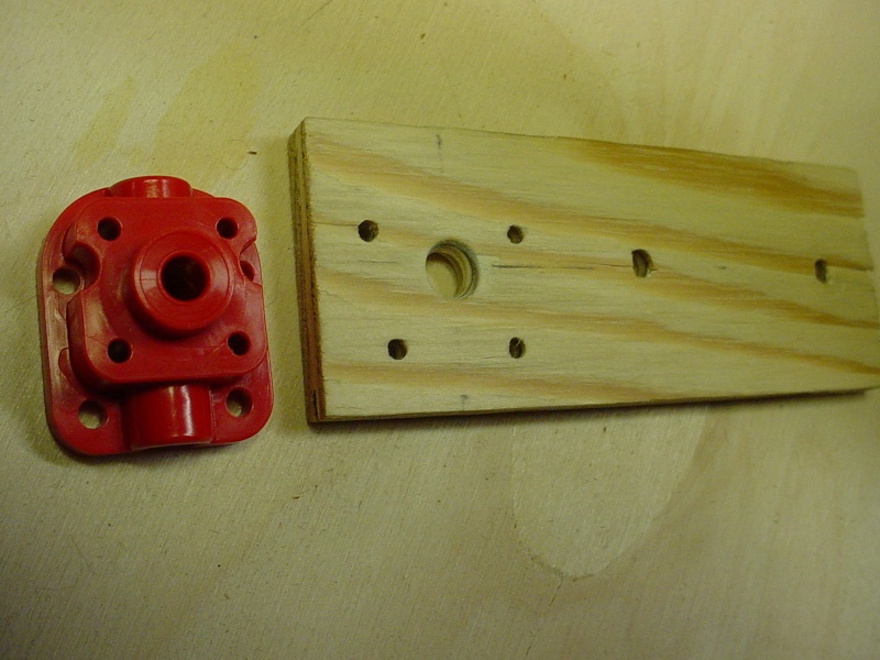
I also made a better "horseshoe" back-plate engine mount for the beam. The first one was 90 degrees clockwise of this pattern, which didn't allow access for adjusting the needle.
Roddie


 Re: Dynomometer build (for air-screws)
roddie wrote:
Hi Kris, Yes.. like Mark Boesen replied. To explain in more detail; a Dyno can help you to tune your engine for optimal performance, by showing you how much weight it's able to pull. One engine may pull 4 ounces when using a certain fuel/prop/cylinder type/glow-head type/number of head gaskets... etc. Many variables... Changing any one of them will affect performance that will be measurable using a dyno.
I'm all for bench running, that's a very good way to get to know the engine and to test different fuels and the right amount of head shims etc. I just don't see what the thrust measure will add to that.
For a given prop the rpm number will give you the power the engine develops. You can use this relatively as you change fuel or other settings.
A dyno is more important for cars and motorcycles where you want to apply a load and see how much power the engines develops. For our engines the prop is the load and the rpm gives you the power (if you have a calibrated prop).
For a high static thrust you simply change to a low pitch and large diameter prop. With this prop you still have the highest thrust (and power) for the highest rpm achieved on that prop....
For me trust versus airspeed is a little more interesting that the static thrust. You can get a feeling for that by using the "prop_power_calculator" for instance.

Surfer_kris- Diamond Member

- Posts : 1912
Join date : 2010-11-20
Location : Sweden
 Re: Dynomometer build (for air-screws)
I am very much in favour of what Roddie is trying to achieve. Nothing beats an empirical testing of thrust given all the variables that can be involved.
While I appreciate that an acceptable way of proofing a configuration can be judged by the revs produced by an engine for a given diameter and pitch of a propeller - other variables come into play that are not covered by tables or calculators.
For example I have eight different 8 x 4 propellers - they all produce differing thrusts that aren't directly relative to the rpm the engine produces. The are made of different materials - plastic, nylon, wood and carbon fibre. They have differing profiles and shapes - square tips, rounded tips, hooked tips and pointed tips. They are not all exactly 8"!
The 8 x 4 that produced the most thrust did so at the lowest revs. It was an 8 x 4 sawtooth carbon fibre blade with pointed tips. Made for me by a friend of mine - both no longer with us.
Rather similar to these


I admire the efforts made by Roddie and am watching them closely. I will follow his progress, learn from his mistakes, copy his design, improve it and build a better one! !!
!!
While I appreciate that an acceptable way of proofing a configuration can be judged by the revs produced by an engine for a given diameter and pitch of a propeller - other variables come into play that are not covered by tables or calculators.
For example I have eight different 8 x 4 propellers - they all produce differing thrusts that aren't directly relative to the rpm the engine produces. The are made of different materials - plastic, nylon, wood and carbon fibre. They have differing profiles and shapes - square tips, rounded tips, hooked tips and pointed tips. They are not all exactly 8"!
The 8 x 4 that produced the most thrust did so at the lowest revs. It was an 8 x 4 sawtooth carbon fibre blade with pointed tips. Made for me by a friend of mine - both no longer with us.
Rather similar to these


I admire the efforts made by Roddie and am watching them closely. I will follow his progress, learn from his mistakes, copy his design, improve it and build a better one!

ian1954- Diamond Member

- Posts : 2688
Join date : 2011-11-16
Age : 70
Location : England
 Re: Dynomometer build (for air-screws)
Surfer_kris wrote:roddie wrote:
Hi Kris, Yes.. like Mark Boesen replied. To explain in more detail; a Dyno can help you to tune your engine for optimal performance, by showing you how much weight it's able to pull. One engine may pull 4 ounces when using a certain fuel/prop/cylinder type/glow-head type/number of head gaskets... etc. Many variables... Changing any one of them will affect performance that will be measurable using a dyno.
I'm all for bench running, that's a very good way to get to know the engine and to test different fuels and the right amount of head shims etc. I just don't see what the thrust measure will add to that.
For a given prop the rpm number will give you the power the engine develops. You can use this relatively as you change fuel or other settings.
A dyno is more important for cars and motorcycles where you want to apply a load and see how much power the engines develops. For our engines the prop is the load and the rpm gives you the power (if you have a calibrated prop).
For a high static thrust you simply change to a low pitch and large diameter prop. With this prop you still have the highest thrust (and power) for the highest rpm achieved on that prop....
For me trust versus airspeed is a little more interesting that the static thrust. You can get a feeling for that by using the "prop_power_calculator" for instance.
You make valid points Kris. Static thrust is still a measureable element.. it's just not exponential.. as are the forces of flight... particularly stunt. Why not know what number is gonna lift your ?/ounce airplane straight up out of a corner?
I'm definitely not disagreeing with you on your points.. torque is another element in which engines are measured. It was important for Aeromodeller Magazine to test the Tee Dee .049 in 1962.. and state it's output power (bph/watts) and maximum torque (ounce/in.) at given rpm's.. on specified fuel. How do you suppose they came up with their numbers?
Roddie
 Re: Dynomometer build (for air-screws)
roddie wrote: It was important for Aeromodeller Magazine to test the Tee Dee .049 in 1962.. and state it's output power (bph/watts) and maximum torque (ounce/in.) at given rpm's.. on specified fuel. How do you suppose they came up with their numbers?
Roddie
I think they ran a calibrated flywheel (with known inertia) and measured the rpm as the engine accelerates. From that you can then calculate the power and torque vs rpm.

Surfer_kris- Diamond Member

- Posts : 1912
Join date : 2010-11-20
Location : Sweden
Page 1 of 3 • 1, 2, 3 
 Similar topics
» Screws For Engines
» 8 cc fuel tank screws
» Phillips Head Tank Screws
» Cox bee tank extenders
» Cox .010 tank screws
» 8 cc fuel tank screws
» Phillips Head Tank Screws
» Cox bee tank extenders
» Cox .010 tank screws
Page 1 of 3
Permissions in this forum:
You cannot reply to topics in this forum

 Rules
Rules

