Log in
Search
Latest topics
» Tee Dee .020 combat modelby 1/2A Nut Today at 10:34 am
» Happy 77th birthday Andrew!
by rdw777 Today at 10:04 am
» Purchased the last of any bult engines from Ken Enya
by sosam117 Today at 8:15 am
» TEE DEE Having issues
by balogh Today at 7:42 am
» Retail price mark-up.. how much is enough?
by rsv1cox Today at 7:36 am
» Cox films/videos...
by Coxfledgling Today at 4:46 am
» My N-1R build log
by roddie Today at 12:32 am
» Landing-gear tips
by roddie Yesterday at 6:17 pm
» Roger Harris revisited
by TD ABUSER Yesterday at 2:13 pm
» My latest doodle...
by roddie Yesterday at 10:43 am
» Chocolate chip cookie dough.........
by roddie Fri Nov 22, 2024 1:13 pm
» Free Flight Radio Assist
by rdw777 Fri Nov 22, 2024 9:24 am
Cox Engine of The Month
Engine thrust meter
Page 1 of 1
 Engine thrust meter
I built one years ago, truly a "red-neck" approach... but it was scaled... although crudely. "This post is for the "visually minded"... as it is "no longer" and I have no photos of it. It consisted of a counter-weighted 25% upper 75% lower pendulum, with a measurement "arc" and a stop. The engine/motor-mount and "rear" counter-weight box (to balance motor-weight) was on the pendulum's top. The pendulum's bottom was fitted with a "pointer/nail". Calibration, was accomplished by "balancing" the pendulum "vertically", and loading the rear end of the weight-box with a diet scale. A stand/frame was built to hold the pendulum, a graph using white poster-board was mounted behind the pendulum's arc, a "D" battery holder, switch and glow-plug connector and a pendulum "safety-lock" and "stop" was also used.
The motor-mount/weight-box had a radial mount for Cox Bee's and prod. back-plates. When tuned and running, the engine mounted to the "balanced" pendulum would swing "left" once unlocked (CCW rotation), causing the lower pendulum to swing "right" into the measurement arc... thus giving a reading on the poster-board scale.
As crude as this is... it "can" be calibrated for performance measurements.. You could even balance-in a tach. holder.
I am working on a similar design principle; "loading" the table on a postage scale... and re-setting the "zero" to display the actual oz. "over fixture weight". This should work. as long as the fixture's "balanced" weight is less than 1 oz.
 Re: Engine thrust meter
I hope you post your results - I have been mulling this over for some time. American Hobbies have a very neat looking dynamometer but it is expensive and they don't appear to have a web site.
The simplest I have seen is

I have also seen a set up wher the engine in simply mounted on a trolley and the pull was measured with a spring balance.
These were all constructed in the days before fancy little rev counters.
There often seems to be an obsession with revs but I always think that it is the ability to measure the power generated by an engine/propeller combination that is important.
There is also the final empirical test - How does the combination fly?
The simplest I have seen is

I have also seen a set up wher the engine in simply mounted on a trolley and the pull was measured with a spring balance.
These were all constructed in the days before fancy little rev counters.
There often seems to be an obsession with revs but I always think that it is the ability to measure the power generated by an engine/propeller combination that is important.
There is also the final empirical test - How does the combination fly?

ian1954- Diamond Member

- Posts : 2688
Join date : 2011-11-16
Age : 70
Location : England
 Re: Engine thrust meter
Simpler is a right angle set of arms on a pivot with one of those fancy digital kitchen scales. If the lever arms are equal, and the pivot adequately free through use of the "tare" button thrust is directly measured.
Downside is the scale gets oily and nasty, even in a plastic bag. (at least it seemed to, I bought a new scale for the kitchen and use this for shop and hobby things now)
I built one from PVC pipe using round headed carriage bolts as "feet" so it would pivot as free as possible...however the feet never stayed put and my hopped up baby stunt bee pulled the whole contraption off the table!
The idea is sound. At some point I plan to rebuilt the apparatus using a thru-bolt and have it all bolted to a weighty plank. The priority level is very low currently.
Phil

pkrankow- Top Poster

- Posts : 3025
Join date : 2012-10-02
Location : Ohio
 Re: Engine thrust meter
How are you able to acheive a true "zero" ? It looks to me that you can only measure thrust between engines.

Cribbs74- Moderator


Posts : 11907
Join date : 2011-10-24
Age : 50
Location : Tuttle, OK
 Re: Engine thrust meter
The real idea is for "performance" tuning an individual engine rather than some specific reading to compare with another engine. All you can tell from the position of the weight is a power comparison. The further away from the engine - the more torque generated.
An engine mounted on a "trolley" pulling against a spring balance would give readings. Accurate - probably not - but a good guide.
An engine mounted on a "trolley" pulling against a spring balance would give readings. Accurate - probably not - but a good guide.

ian1954- Diamond Member

- Posts : 2688
Join date : 2011-11-16
Age : 70
Location : England
 Re: Engine thrust meter
Ron, theoretically; a vertically balanced "pendulum" as in my design, should give accurate readings for different engines. Balancing the pendulum to ea. engine is accomplished by counter-weighting the opposite side of the mount, at the top of the pendulum. This can be done with the weight-box... or even simpler; a sm. bottle w/cap, to hold enough water to counter-weight the mount with engine/prop. and possibly a "tach./mount" installed. After mounting your engine, the pointer should read slightly positive on the graph with an empty bottle. Adding water to the bottle will bring it back to "zero".. or "balanced". If using an external fuel tank, it should be mounted on/over the balance point so that; as fuel is consumed... it doesn't unbalance the pendulum.Cribbs74 wrote:How are you able to acheive a true "zero" ? It looks to me that you can only measure thrust between engines.
The pendulum's "length" depends on where the pivot/swing-point is placed. Ideally; a pendulum with a series of graded vertical holes for the swing-pin would help with initial set-up/calibration. You want enough pendulum weight "below" the pivot, to provide a "75% of max." reading on the scale, when testing your most powerful engine/prop. set-up. For testing "Cox" .049 engines; it should not require more than 8 ounces of force, to move the pendulum to it's maximum reading on the scale. This should produce "healthy engine" readings in the 50-70% on the scale ... (4-6 oz. of thrust)
It is important to note; that the movement of a pendulum is NOT "linear" but "exponential". It will take more force to move it, as the angle increases from vertical (zero)...to full extension (100% of the scale). This is where it is more accurate to calibrate the scale in "ounce" increments. The distance between graduations on the scale will be closer together, as the pendulum angle increases.
 Re: Engine thrust meter
Being on lay-off... "my" priority levels are all out of whack... what I "actually" do vs. what I "should" do.pkrankow wrote:Simpler is a right angle set of arms on a pivot with one of those fancy digital kitchen scales. If the lever arms are equal, and the pivot adequately free through use of the "tare" button thrust is directly measured.
Downside is the scale gets oily and nasty, even in a plastic bag. (at least it seemed to, I bought a new scale for the kitchen and use this for shop and hobby things now)
I built one from PVC pipe using round headed carriage bolts as "feet" so it would pivot as free as possible...however the feet never stayed put and my hopped up baby stunt bee pulled the whole contraption off the table!
The idea is sound. At some point I plan to rebuilt the apparatus using a thru-bolt and have it all bolted to a weighty plank. The priority level is very low currently.
Phil
Here's an idea for the "digital-scale" thrust meter. A balanced "see-saw beam" principal. Either vertical or horizontal arrangement would evenly/accurately load the scales table. If the scale must be "level"... then the vertical pivot would have to be used and the engine mounted facing upward.
[edited]
Vertical arrangement; the beam should be "substantial" (1" sq. alum. tubing) about 3 ft. long with a pivot point "equidistant" from the engine mount centerline, to the opposite end of the beam that contacts the scale. Attach a rubber "foot" to the beam, where it will contact the scale's table. The base/pivot-point would be firmly mounted and have 2 "ears" with bearing holes to support the beams' pivot pin. (see-saw). Mount a "U" bolt over the beams "scale" end, to limit it's travel to about 1/2" above the scale's table. A "cue" lever could be built-in, to lower/raise the beam onto/from the scale's table.
Run the engine "beam raised" with the scale on the other end, centered "under" the beams' rubber foot. "Lower" the beam, to contact the scale for thrust readings. Depending on how much fuel is in the tank, you will get slightly higher thrust readings as fuel is consumed. Having 1/2" of beam-travel permits mounting an external tank independently from the beam, using a long enough fuel line. This would allow accurate measurements throughout the entire engine run.
A shroud/shield should be used for safety... No more "oily scale".
We all know you didn't buy that digital scale for the kitchen Phil....

 Re: Engine thrust meter
The first one was assumed to be bought for the kitchen. The second was actually bought for the kitchen.
Phil
Phil

pkrankow- Top Poster

- Posts : 3025
Join date : 2012-10-02
Location : Ohio
 Thrust meter
I don't know how many of you are members at RC Universe, but they have a topic in the 1/2A & 1/8A airplanes forum on this very subject.
Search for '1/2A Thrust-o-meter' to find it.
There are several different methods shown and discussed, as well as CombatPigg's extensive testing of various engines and prop combinations!
Search for '1/2A Thrust-o-meter' to find it.
There are several different methods shown and discussed, as well as CombatPigg's extensive testing of various engines and prop combinations!

VUgearhead- Gold Member

- Posts : 155
Join date : 2013-07-02
Age : 57
Location : Boynton Beach, FL
 Re: Engine thrust meter
May I suggest the simple adaptation of postage scale as a model engine thrust meter?
(All patent rights graciously waived)
SD
(All patent rights graciously waived)
SD

SuperDave- Rest In Peace

- Posts : 3552
Join date : 2011-08-13
Location : Washington (state)
 Re: Engine thrust meter
back to this... I received my order for 2 of these little digital fishing scales in the mail this past week... (for $3/ea. I couldn't resist) and my speed-contest piston/cylinder arrived a day later!
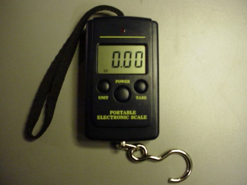
The plan is... to build a sm. test fixture (1' x 2' footprint) engine/motor dyno; capable of measuring thrust via an airscrew. Proposed is; a "tub" to float a buoyant platform with a pylon for mounting a propulsion unit. This mount will have a direct linear pull on the digital scale. Travel limit will be less than 1"... and leveling-cups will balance the float. Safety rails will prevent the float from lifting. An aero-dynamic shield/bag protects the scale from propulsion wastes.
This Dyno is something I've always wanted to build for my Cox engines... and have it be close to accurate. It should at least; give accurate comparisons; along with a tach... between propellers.
The build will be soon.
 Re: Engine thrust meter
Just hook the scale to the tail of the airplane like a stooge. Quit wasting yer time getting fancy.
Phil
Phil

pkrankow- Top Poster

- Posts : 3025
Join date : 2012-10-02
Location : Ohio
 Re: Engine thrust meter
I'm really interested to see one of these concepts put to the test.
How about this:
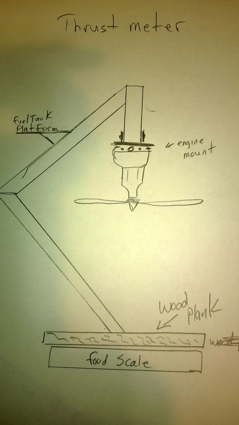
You might want to zero it and remove it to crank, then set it on the scale. And for the Bee, fill it, then plug a vent and use an external tank connected to the other vent.
How about this:

You might want to zero it and remove it to crank, then set it on the scale. And for the Bee, fill it, then plug a vent and use an external tank connected to the other vent.
_________________
Don't Panic!
...and never Ever think about how good you are at something...
while you're doing it!
My Hot Rock & Blues Playlist
...and never Ever think about how good you are at something...
while you're doing it!
My Hot Rock & Blues Playlist

RknRusty- Rest In Peace

- Posts : 10869
Join date : 2011-08-10
Age : 68
Location : South Carolina, USA
 Re: Engine thrust meter
A "pull (hanging) scale" and fixture is what I wanted to go with, in order to have a tach mount... a bracket for an external fuel tank, and "quick-change modules" for either radial or beam engine mounts; to easily remove an engine for plug/cylinder changes etc.RknRusty wrote:I'm really interested to see one of these concepts put to the test.
How about this:
You might want to zero it and remove it to crank, then set it on the scale. And for the Bee, fill it, then plug a vent and use an external tank connected to the other vent.
A buoyant foam block with a central pylon-style engine mount, cut to fit inside a small water tub with minimal "side to side" clearance and about 1" of linear travel, would not have much (if any) linear resistance when floating in/on the water. (think of a motorboat on a trailer... and the same motorboat floating in the water and trying to "pull" either one using a rope) I think this less resistive approach will transfer to a more accurate scale reading, during the running of a prop/engine combo. The digital scale's hook will attach directly to a rigid hook on the back of the pylon/engine mount.
 Re: Engine thrust meter
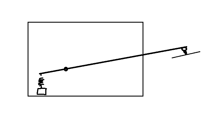
ok, so here's my 'Torque-Tester' i've thought of building years ago, but never did.
I'd use a small light weight 'fulcrum' maybe aluminum, by offsetting the pivot point it would make the scale more sensitive to engine pull and keep oil off the scale.
Last edited by Mark Boesen on Mon Dec 02, 2013 10:20 pm; edited 2 times in total
 Re: Engine thrust meter
Sure that would work Phil... I'm sure it doesn't surprise you, that I'm over-thinking this. I do that with everything!pkrankow wrote:Just hook the scale to the tail of the airplane like a stooge. Quit wasting yer time getting fancy.
Phil
Your idea for "at the field" testing is good too...
I guess I just like the idea a "purpose-built" means of performance bench-testing an engine/prop combo.. before I put it on my airplane.
Roger
 Re: Engine thrust meter
Fine, screw the engine to the end of a 2x2 with wheels and set it up like a stooge.
Phil
Phil

pkrankow- Top Poster

- Posts : 3025
Join date : 2012-10-02
Location : Ohio
 Re: Engine thrust meter
Got here through Eric's link regarding home build dyno's for model aircraft engines.ian1954 on Oct 18, 2013 wrote:There often seems to be an obsession with revs but I always think that it is the ability to measure the power generated by an engine/propeller combination that is important. There is also the final empirical test - How does the combination fly?
Yes, truly spoken. One can get a Cox to whine above its maximum horsepower RPM, but it is the amount of thrust produced by the engine prop combination that counts. This is why the antiquated .60 Brown Jr. ignition, output only 1/4 BHP turning a 14 or 15 inch prop at under 6,000 RPM was able to pull an 8 foot wingspan free flight. A comparible modern day .15 with the same BHP output turning an 8 inch prop at 15,000 RPM just won't put the wind past such a large airframe.
It is the combination of the entire system, engine - prop - plane, all must work together in unison.

GallopingGhostler- Top Poster


Posts : 5724
Join date : 2013-07-13
Age : 70
Location : Clovis NM or NFL KC Chiefs
 Similar topics
» Dynomometer build (for air-screws)
» Template for the .15 Engine Pylon on my 3-Meter B.O.T.
» engine thrust
» 'Fencing' with the 3-Meter B.O.T. !!!
» Power Pod for my 3-Meter Bird of Time Sailplane
» Template for the .15 Engine Pylon on my 3-Meter B.O.T.
» engine thrust
» 'Fencing' with the 3-Meter B.O.T. !!!
» Power Pod for my 3-Meter Bird of Time Sailplane
Page 1 of 1
Permissions in this forum:
You cannot reply to topics in this forum

 Rules
Rules

