Log in
Search
Latest topics
» Happy 77th birthday Andrew!by Admin Today at 12:34 pm
» Roger Harris revisited
by getback Today at 12:30 pm
» Retail price mark-up.. how much is enough?
by rsv1cox Today at 12:23 pm
» Tee Dee .020 combat model
by 1/2A Nut Today at 10:34 am
» Purchased the last of any bult engines from Ken Enya
by sosam117 Today at 8:15 am
» TEE DEE Having issues
by balogh Today at 7:42 am
» Cox films/videos...
by Coxfledgling Today at 4:46 am
» My N-1R build log
by roddie Today at 12:32 am
» Landing-gear tips
by roddie Yesterday at 6:17 pm
» My latest doodle...
by roddie Yesterday at 10:43 am
» Chocolate chip cookie dough.........
by roddie Fri Nov 22, 2024 1:13 pm
» Free Flight Radio Assist
by rdw777 Fri Nov 22, 2024 9:24 am
Cox Engine of The Month
Spray bar holes positioning
Page 1 of 1
 Spray bar holes positioning
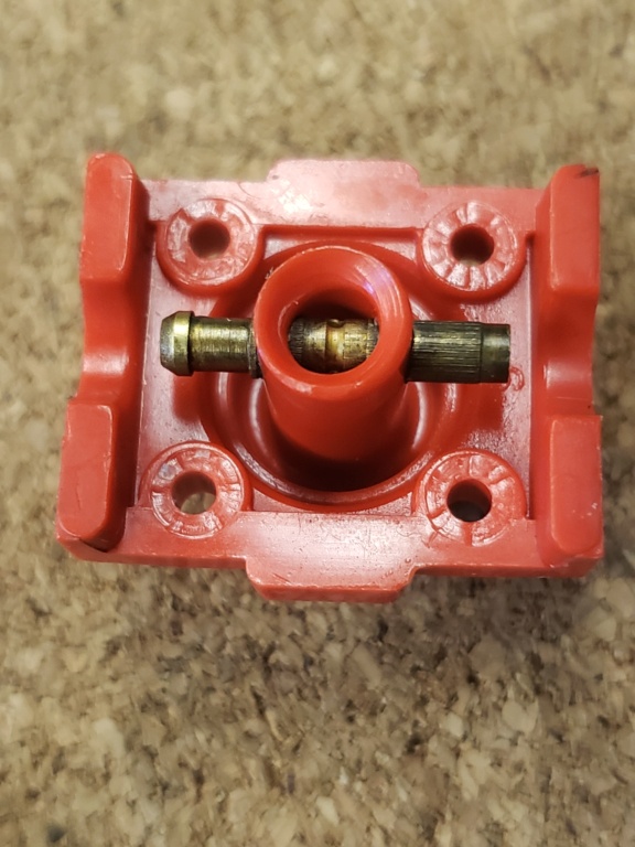
I've got this postage stamp backplate all ready to go back together but don't know which way to have the TWO holes orientated.. One facing the firewall, and one facing the reed? Seems like it would wash the firewall..

Michpatriot- Gold Member

- Posts : 157
Join date : 2023-01-12
 Re: Spray bar holes positioning
Normally, the engine cylinder would be mounted upright with the needle valve pointing horizontal to the inside of the C/L circle and the fuel nipple to the outside, for short fuel line length to a profile fuselage mounted tank.
By mounting the back oriented as described above, then the EB-1 holes are aligned to match the bolt spacing of the Cox tank reed valve engines.
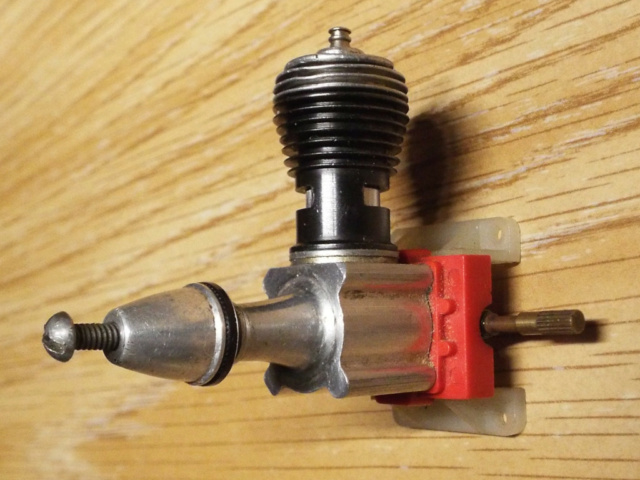
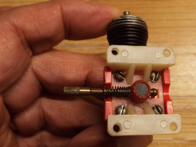
However, if there is not a need to match such bolt pattern, you can orient the engine however you want, but the mount is designed to have the venturi needle and nipple face the open sides of the mount.
Once the needle, its spring and crankcase are removed, the mount can be positioned in place over top the back.
By mounting the back oriented as described above, then the EB-1 holes are aligned to match the bolt spacing of the Cox tank reed valve engines.


However, if there is not a need to match such bolt pattern, you can orient the engine however you want, but the mount is designed to have the venturi needle and nipple face the open sides of the mount.
Once the needle, its spring and crankcase are removed, the mount can be positioned in place over top the back.

GallopingGhostler- Top Poster


Posts : 5724
Join date : 2013-07-13
Age : 70
Location : Clovis NM or NFL KC Chiefs
 Re: Spray bar holes positioning
I think the question is about orientation of the jets in the spray bar. You want them perpendicular to the venturi bore.
http://www.nclra.org/TechTopics/NeedleValvePlacement/NeedleValveAlignment.pdf
http://www.nclra.org/TechTopics/NeedleValvePlacement/NeedleValveAlignment.pdf

gkamysz- Gold Member

- Posts : 417
Join date : 2018-02-22
Location : Chicagoland
 Re: Spray bar holes positioning
I thought those spray bars had one hole facing downstream toward the reed.

crankbndr- Top Poster

- Posts : 3109
Join date : 2011-12-10
Location : Homestead FL
 Re: Spray bar holes positioning
gkamysz wrote:I think the question is about orientation of the jets in the spray bar. You want them perpendicular to the venturi bore.
That would make sense based on Bernoulli's Principle. With the spray bar jets perpendicular to the airflow, they would be located in an area of highest air velocity, consequently, the pressure would be the lowest or producing the greatest fuel draw.
crankbndr wrote:I thought those spray bars had one hole facing downstream toward the reed.
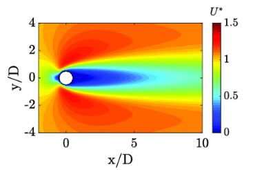
This alignment also has validity. The measurement of pressures of flows around a cylinder shows the lowest pressure at the downstream side of the cylinder (spray bar). If that were the case and the spray bar had a single hole, then directly facing the reed might provide the best draw due the lowest pressure measurement.
What was not entirely clear in the article was the impact of venturi size. In the last paragraph, it was stated that the difference in drawing ability was changed by 45% when comparing the .345 vs the .375 venturi diameter, however, he did not state which was higher. I'm assuming (@#$%) that the .345" venturi had a higher draw simply due to the increased velocity. That's ma' story, corrections welcomed.
Last edited by andrew on Fri Feb 24, 2023 2:43 pm; edited 1 time in total
 Re: Spray bar holes positioning
Michpatriot wrote:I've got this postage stamp backplate all ready to go back together but don't know which way to have the TWO holes orientated.. One facing the firewall, and one facing the reed? Seems like it would wash the firewall..
This is interesting. Can you show us a picture of the spraybar? I've never seen one with two holes. The only two hole spraybar I've seen is on a Fox 35.
The Inquisitive Mark
batjac- Diamond Member


Posts : 2375
Join date : 2013-05-22
Age : 61
Location : Broken Arrow, OK, USA
 Re: Spray bar holes positioning
Yup,  Mark.
Mark. 
OK, https://www.coxengineforum.com/t17072-bad-reed-symptoms#221222
Thought was in the other thread, so I misunderstood. Yes, I think someone more familiar, like Ken could answer. I have never removed the spray bar from a 290 engine, only have the 190 and never removed the spray bar.
So, ball is in another's court.
 Mark.
Mark. OK, https://www.coxengineforum.com/t17072-bad-reed-symptoms#221222
Michpatriot today at 8:50 am wrote:Still not sure on the spray bar positioning, with two holes, 180° apart on the bar..do I face one toward the fire wall and that would leave the other one facing the reed?? Seems like it would wash the firewall? Ken Cook to the rescue!
Thought was in the other thread, so I misunderstood. Yes, I think someone more familiar, like Ken could answer. I have never removed the spray bar from a 290 engine, only have the 190 and never removed the spray bar.
So, ball is in another's court.

GallopingGhostler- Top Poster


Posts : 5724
Join date : 2013-07-13
Age : 70
Location : Clovis NM or NFL KC Chiefs
 Re: Spray bar holes positioning
If the spray bar you’re referring to has a groove machined in the center, with two holes (jets) drilled 180° apart, then insert the spray bar so that the holes are set to the left and right hand sides of the back plate. In other words, you want the jets perpendicular to airflow, not parallel as in the usual 190/290 engine. That spray bar is very rare, used less than six months during 1968.

Mudhen- Gold Member

- Posts : 489
Join date : 2011-09-19
 Re: Spray bar holes positioning
I used to tinker with these for the tach race, I opened the hole up slightly and it did not help at all.
Mark B yahoo site (excellent site, now gone for faceplant) had and article by Larry Renger on how to hop up the Hyper Viper.
One tip was to turn the sprayer hole a few degrees away from strait downstream.
PS WELCOME BACK MUDHEN!!!!
Mark B yahoo site (excellent site, now gone for faceplant) had and article by Larry Renger on how to hop up the Hyper Viper.
One tip was to turn the sprayer hole a few degrees away from strait downstream.
PS WELCOME BACK MUDHEN!!!!

crankbndr- Top Poster

- Posts : 3109
Join date : 2011-12-10
Location : Homestead FL
 Re: Spray bar holes positioning
I have one like that. The engine is rough, but it does have a early thin wall cylinder, red postage stamp, exhaust shield, 128tpi needle and thin nose case.

gkamysz- Gold Member

- Posts : 417
Join date : 2018-02-22
Location : Chicagoland

Michpatriot- Gold Member

- Posts : 157
Join date : 2023-01-12
 Re: Spray bar holes positioning
This backplate is sitting for now..I ended up using the grey backplate I got from 1\2a Dave with a single hole aimed directly forward..it runs the best its ever run on bladder today! I bored the venture canned the screen and shaped the inlet..the new style reed didn't spin freely under the clip so I went with the Copper byrilzziudm one and it works fine.

Michpatriot- Gold Member

- Posts : 157
Join date : 2023-01-12
 Re: Spray bar holes positioning
Michpatriot wrote:Groove in center two hole spray bar.
Wow. Never seen that before. Maybe I'll pick one up someday for my collection.
The Incomplete Mark

batjac- Diamond Member


Posts : 2375
Join date : 2013-05-22
Age : 61
Location : Broken Arrow, OK, USA
 Re: Spray bar holes positioning
The fact that he's using bladder pressure is going to make little to no difference where the holes are. Fuel doesn't spray like a faucet through the holes, it drips. All of my spraybars are this style which I've used for Norvel and Tee Dee's. For Tee Dee use, I copied a ACE version replacement and made this part from aluminum. I then JB weld the spraybar into this part.
Due to the way the Goldberg mounts hold the backplate off of the firewall, this might be beneficial prior to starting. Fill your bladder, pinch it off. Point the engine nose high and release the pinch off and purge the air from the bladder listening for air until fuel comes out and pinch off. Now holding the plane level, open the pinch off and watch the fuel drip out of the back of the engine and adjust the needle until the drops are about 3/4" - 1" apart in the stream. Pinch off and prime engine, hook up battery and flip until it runs on prime and release the pinch off. The engine should be rich at this point requiring the needle to go in but you might have to pinch the fuel line until you can adjust the needle.
Just so that your aware, the gray backplates are very weak and prone to splitting where the needle passes through the venturi stack. This can even cause the spraybar to rotate and not the needle itself. I have brand new engines with them already split. This really isn't a issue using bladder pressure but in the event you switch back to suction, it causes problems. I don't know what size you drilled the venturi out to. I will say that 11/64" is about as far as I would go using suction, you can open it further with bladder pressure.

Ken Cook- Top Poster

- Posts : 5642
Join date : 2012-03-27
Location : pennsylvania
 Similar topics
» Please confirm Medallion NVA's
» Medallion Spray bar
» Black Widow setup
» P-38 Lightning-Roddie style..
» Strange, this Spitfire engine has two holes
» Medallion Spray bar
» Black Widow setup
» P-38 Lightning-Roddie style..
» Strange, this Spitfire engine has two holes
Page 1 of 1
Permissions in this forum:
You cannot reply to topics in this forum

 Rules
Rules


