Log in
Search
Latest topics
» My N-1R build logby roddie Today at 12:32 am
» Happy 77th birthday Andrew!
by akjgardner Today at 12:27 am
» TEE DEE Having issues
by TD ABUSER Yesterday at 9:43 pm
» Landing-gear tips
by roddie Yesterday at 6:17 pm
» Roger Harris revisited
by TD ABUSER Yesterday at 2:13 pm
» Tee Dee .020 combat model
by Ken Cook Yesterday at 1:41 pm
» Retail price mark-up.. how much is enough?
by Ken Cook Yesterday at 1:37 pm
» My latest doodle...
by roddie Yesterday at 10:43 am
» Chocolate chip cookie dough.........
by roddie Fri Nov 22, 2024 1:13 pm
» Purchased the last of any bult engines from Ken Enya
by sosam117 Fri Nov 22, 2024 11:32 am
» Free Flight Radio Assist
by rdw777 Fri Nov 22, 2024 9:24 am
» Funny what you find when you go looking
by rsv1cox Wed Nov 20, 2024 3:21 pm
Cox Engine of The Month
Landing-gear 1/2-A variations
Page 1 of 1
 Landing-gear 1/2-A variations
Landing-gear on 1/2A size (and smaller..) model airplanes is not always preferred.. but I’ve always felt that it adds a scale realism and is also functional.
There are pros and cons, as one can imagine. If a model is intended to launch by ROG (Rise off Ground) then a landing-gear is obviously required. If the model must land on pavement, then it will need an undercarriage to protect the airframe from shock and abrasion. These points I would call “pros”.
Another “pro” is being able to tweak the models’ center of gravity via wheel-weight.. which I would consider to be a functional advantage. The wire-struts can also be adjusted (bent) fore/aft providing additional c/g trimming.
Some “cons” might be the added weight and aerodynamic-drag induced to a model that was built for a certain purpose. A control-line combat model (often a flying-wing) wouldn’t have a landing-gear. Scratch-builders may elect to omit L/G, if none was specified or illustrated on a plan or drawing. Even “if” a gear is shown.. some people don’t want or feel the need to fabricate one. Keep in mind, that a tail-dragger gear-design in a scale-like location on a small model could cause nose-over crashes when taking-off or landing.. especially on a grass field.
Materials usually include music-wire for the strut(s) which must be formed (bent) with an overall length to account for a “mounting” to the model. A strut formation must be long enough (with a subject wheel-tire mounted) to provide adequate clearance for subject propeller(s) and have an axle; long enough to accept a wheel or ski and a retention collar. Wire diameter for “mains” on a 1/2A model is generally .047”/.062”. (1.2/1.6mm). Music wire in these sizes is relatively easy to source. K & S metals may still offer 36” lengths.. which is what I’ve bought. A single 12” length is generally enough material to form an inverted “V” gear for most half-A tail-draggers. A tail-skid can be as simple as a toothpick or sm. hardwood dowel.
I designed my 1st ever tri-cycle gear for a self-designed profile Lockheed T33 for the CEF 2017/18 Speed Contest. The wire is .062” dia. I used an inverted-“V” for the mains located approx. mid-chord in the fuses’ wing-slot and angled straight-down (90 degrees) The nosegear mount ties-into the lower beam engine-mount; is slightly longer than the mains.. and is angled slightly aft.. in an effort to dampen the shock of landing.
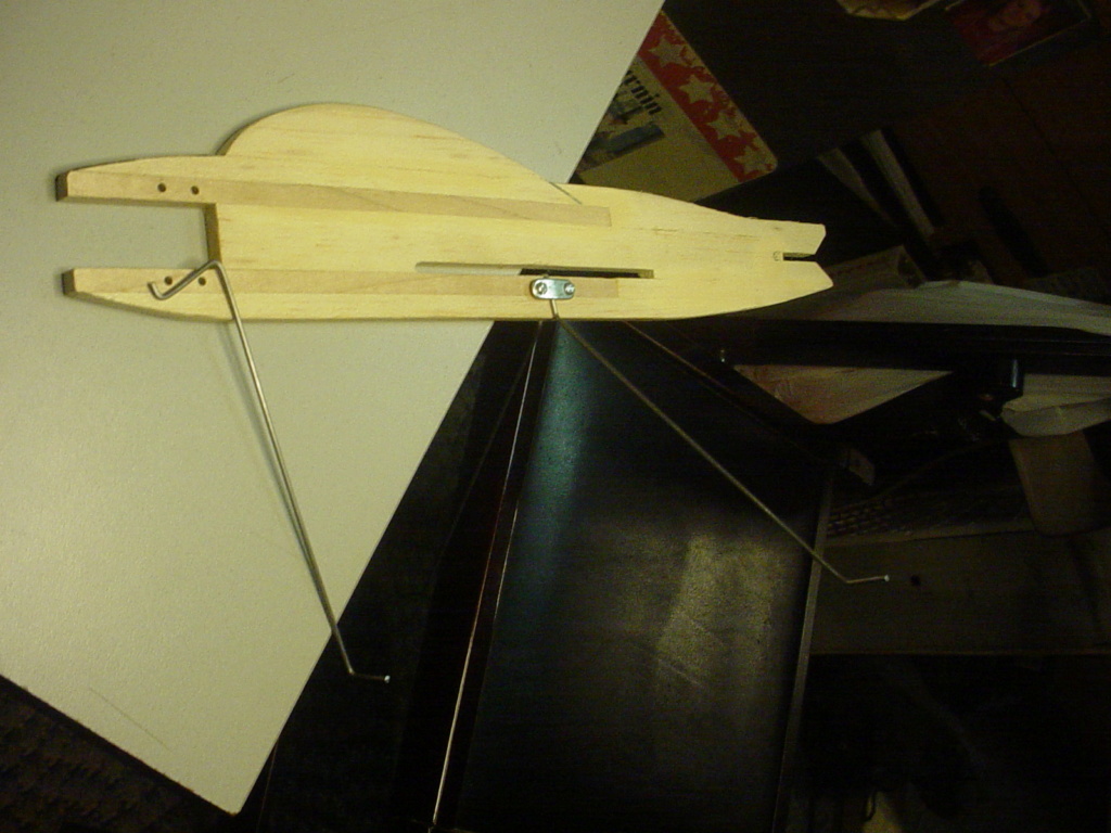
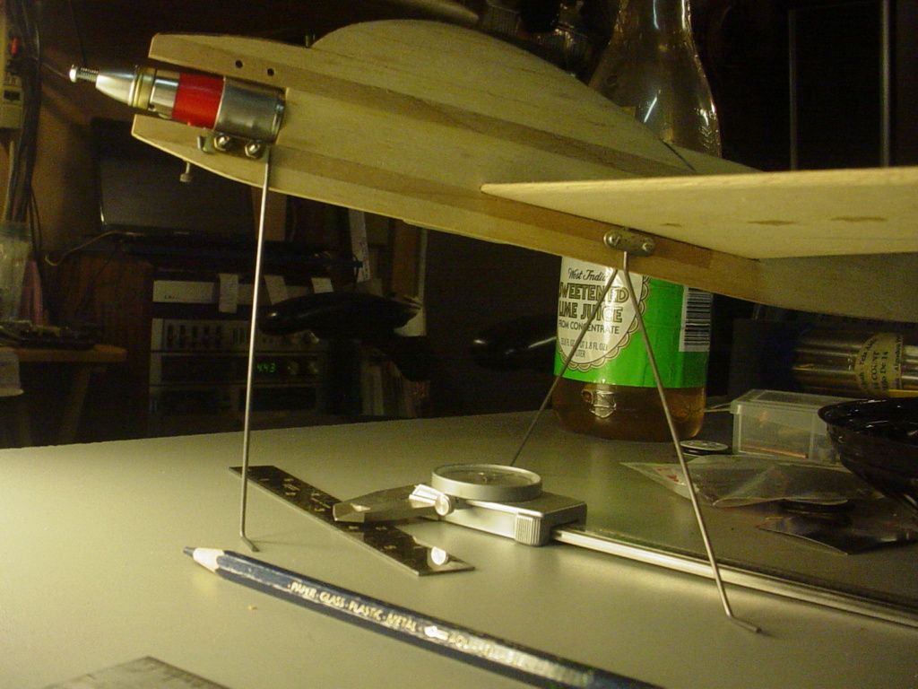
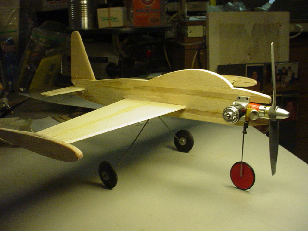
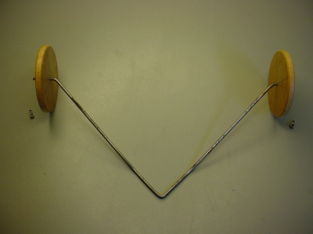
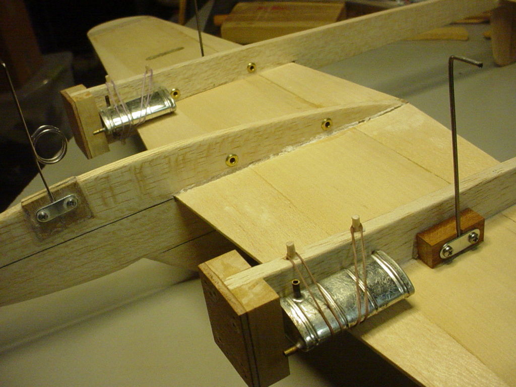
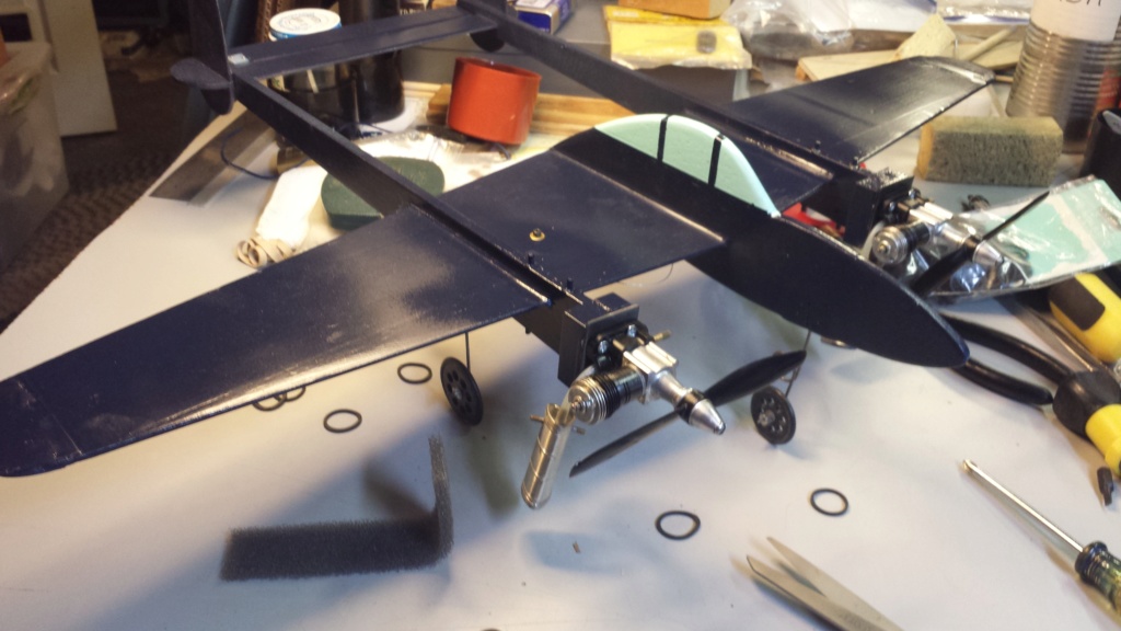
More recently I designed my 2nd half-A C/L model scratch-build of yet another Lockheed warbird; My profile P38 which I would design a different-style tricycle gear for. Its’ twin-booms/engine-nacelles required independent main-struts to provide for straight-ahead tracking.
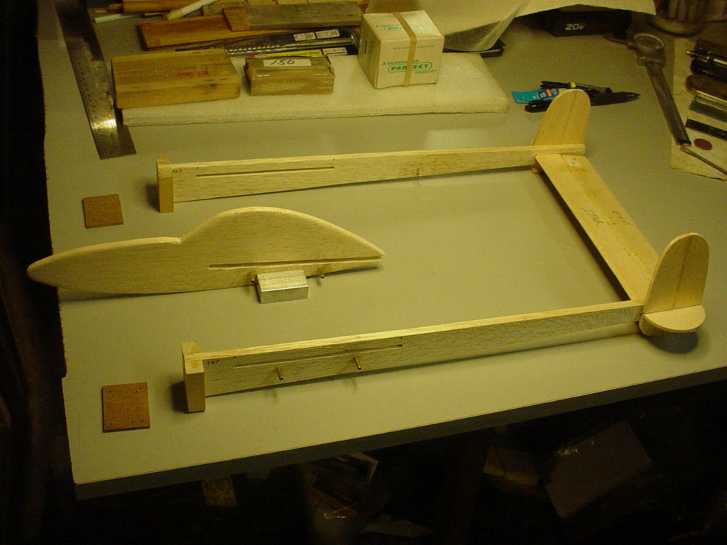
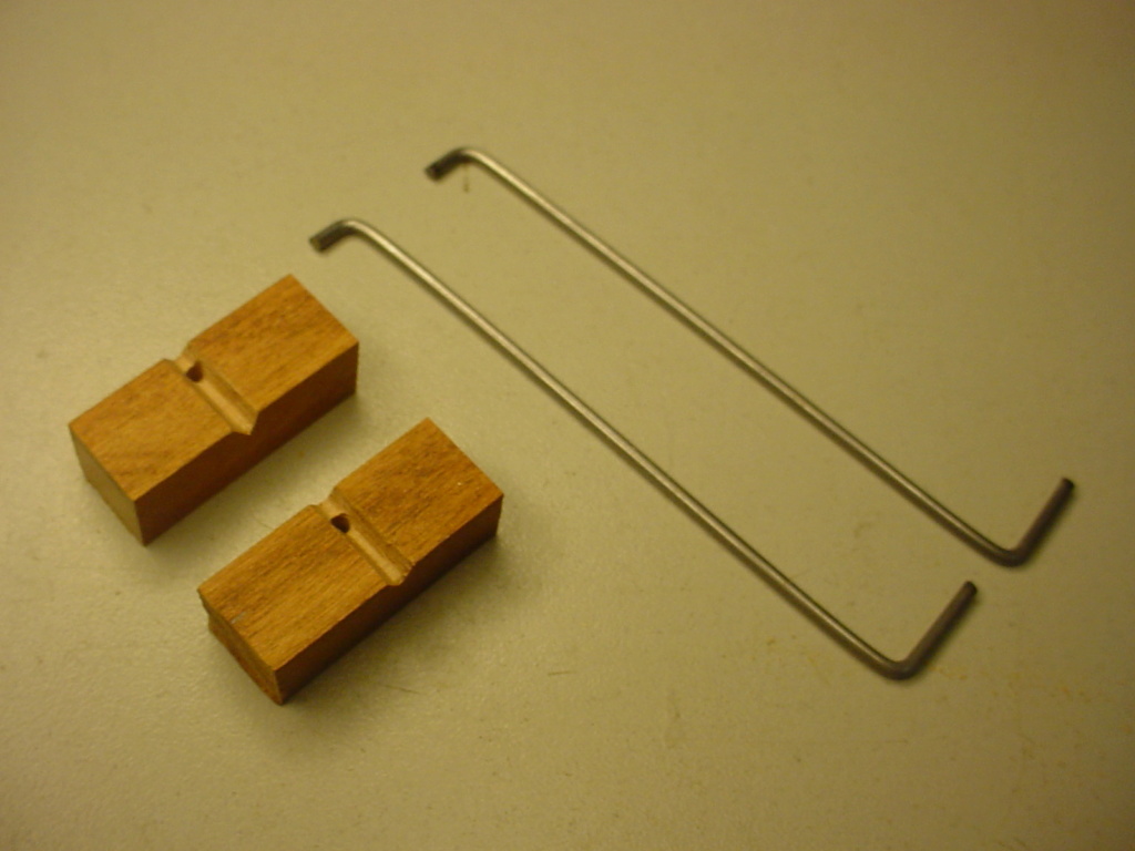
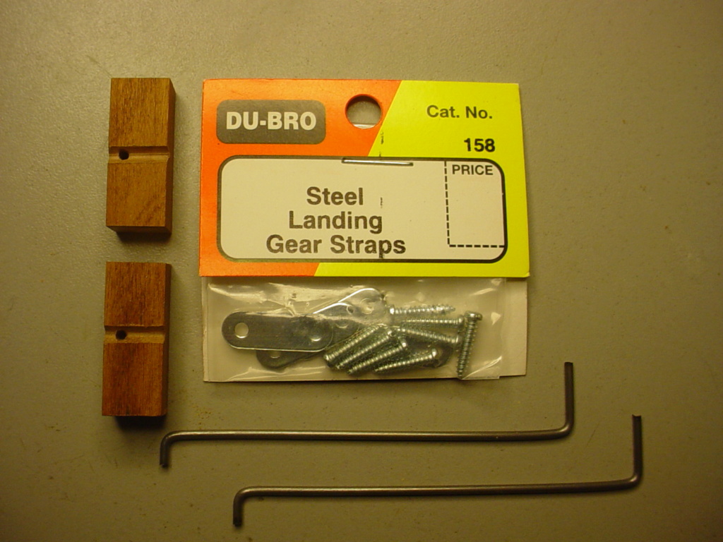
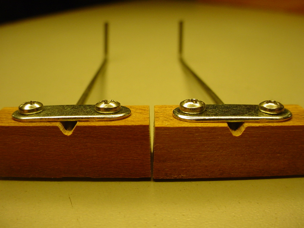
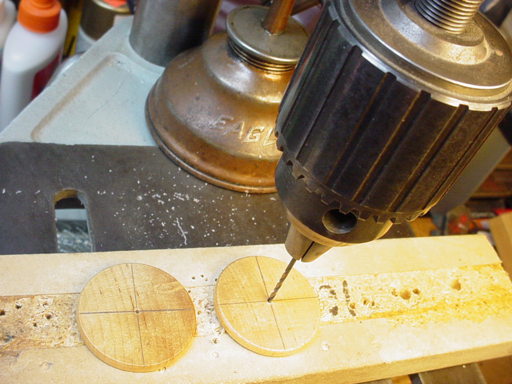
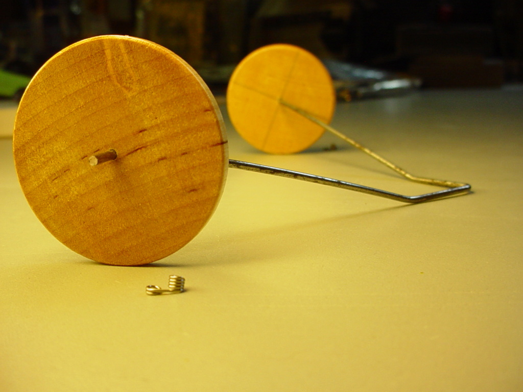
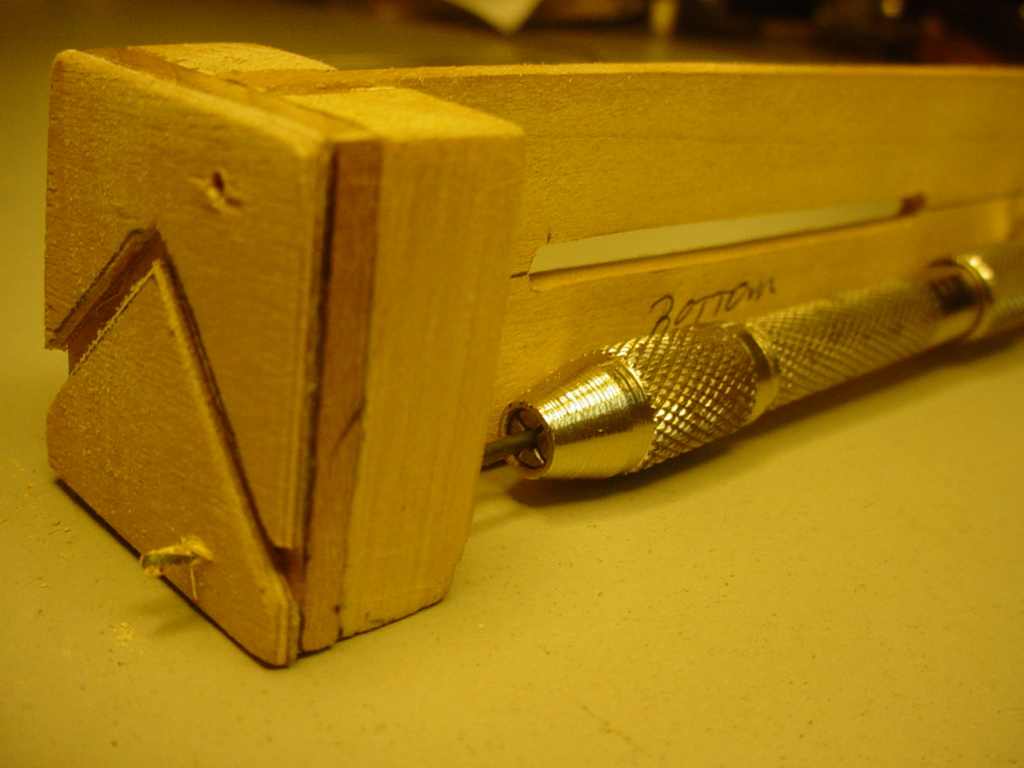
Here’s how I did the P38’s nose-gear..
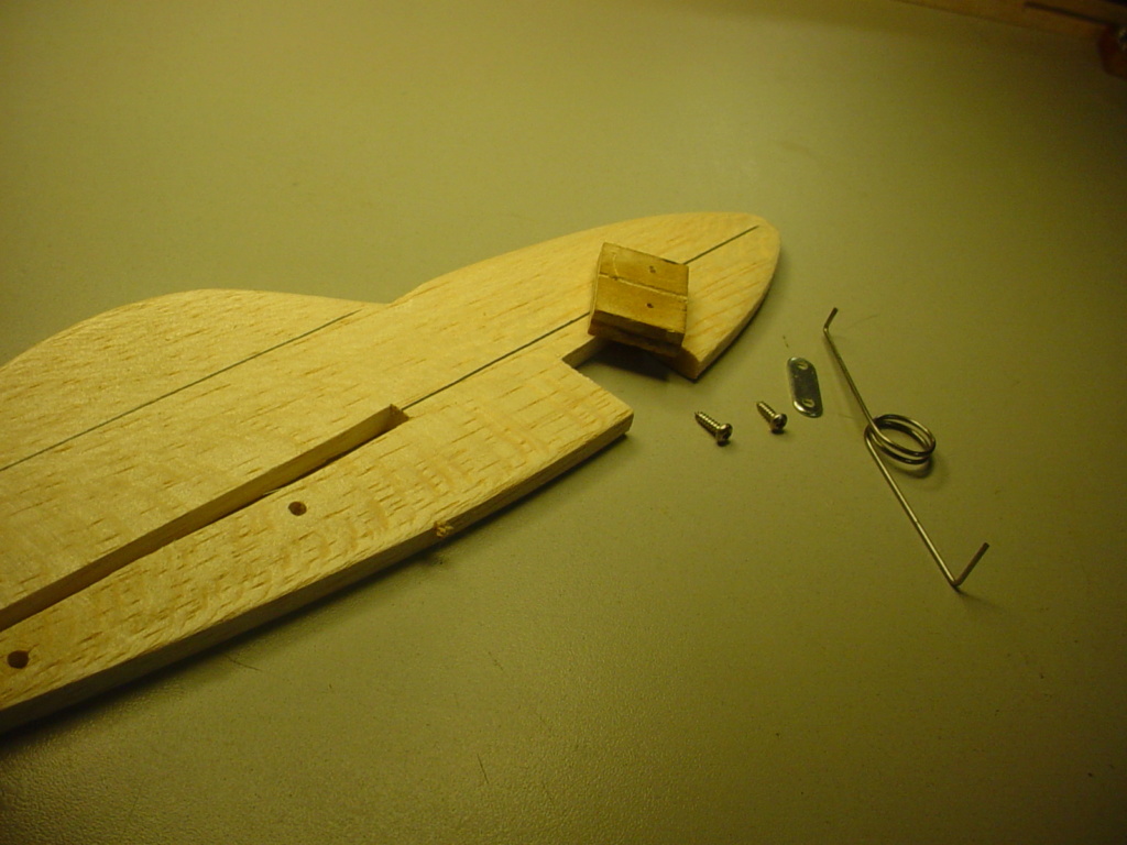
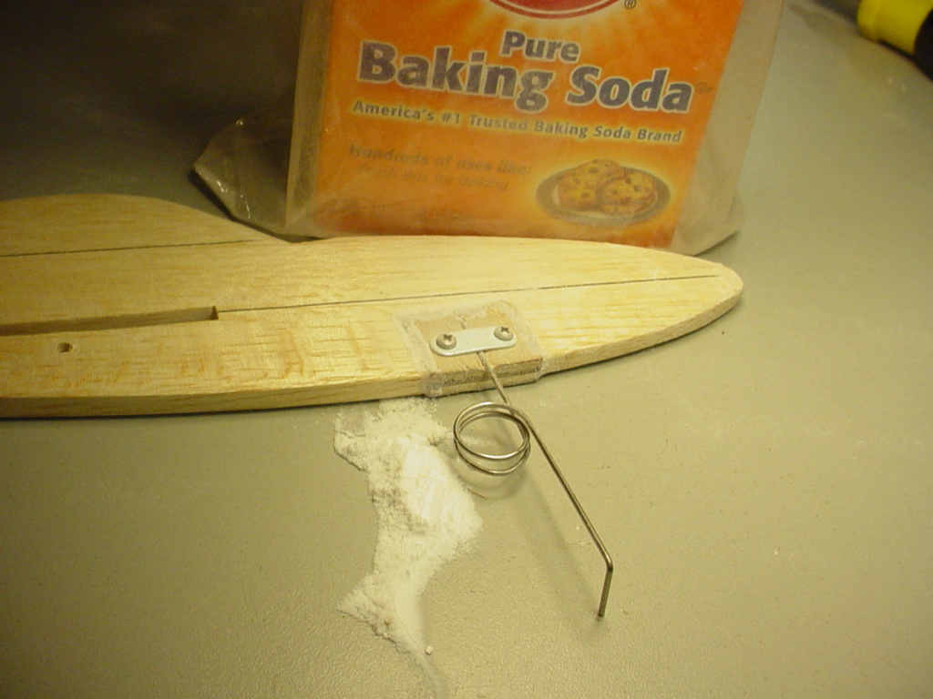
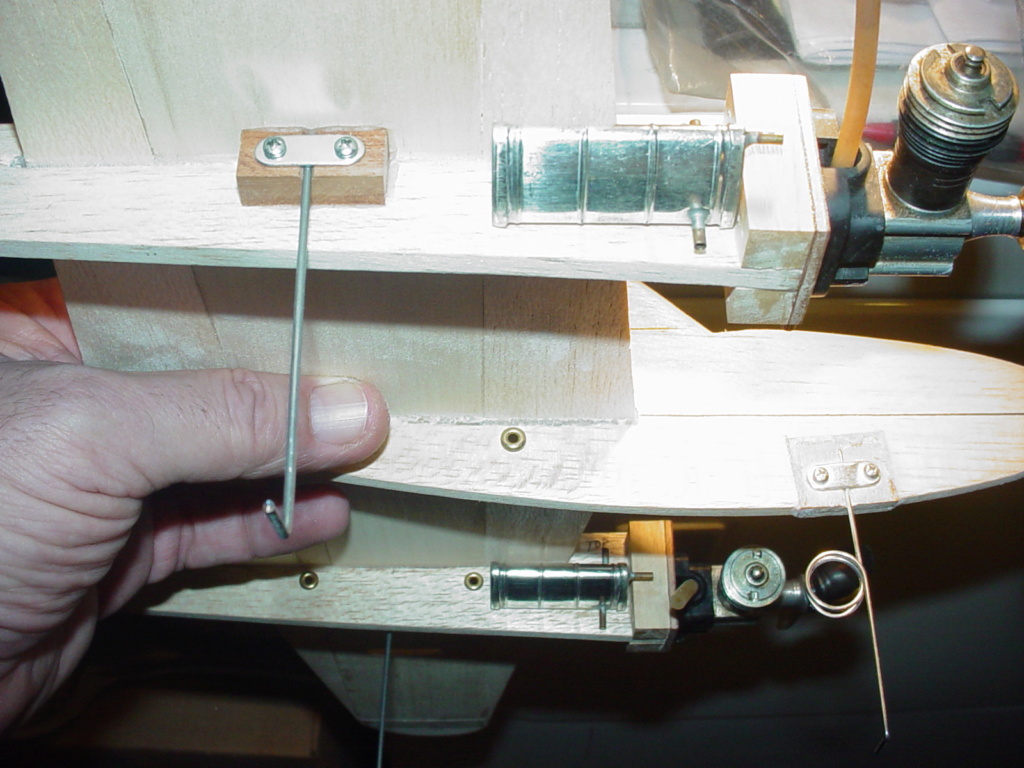
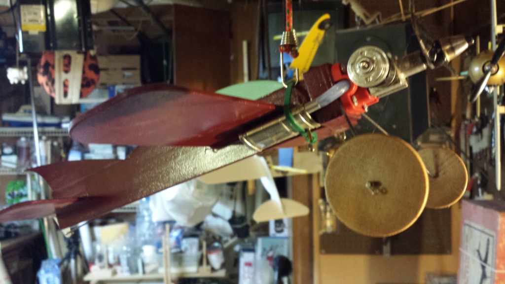
My very 1st experimentation with a scale-like tail-dragger gear-design was what I came up with for the 1st annual CEF profi-scale speed-contest, in my 16” span model of the Grumman F8F-2 Bearcat/Rare-Bear.
I wanted scale-like (independent) gear-struts.. UNLIKE the common "inverted V" that is often found WAY up-front on profile model kits.. or saddled in the fuse's wing-slot and strapped-against plywood nose doublers.
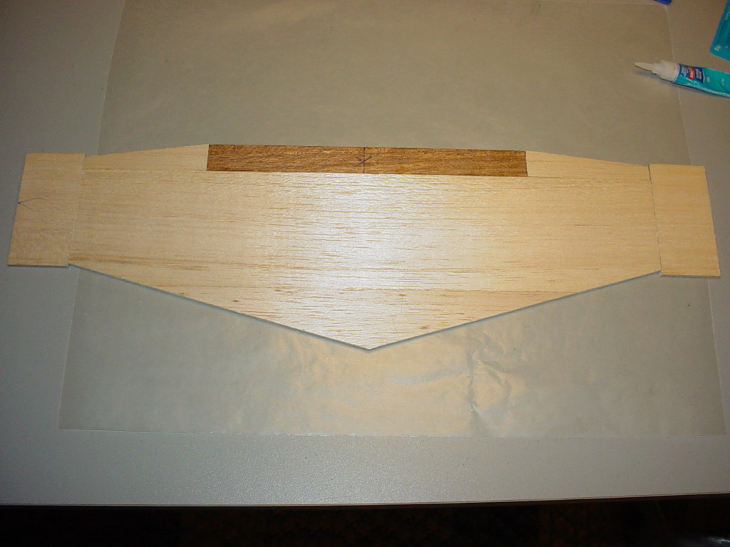
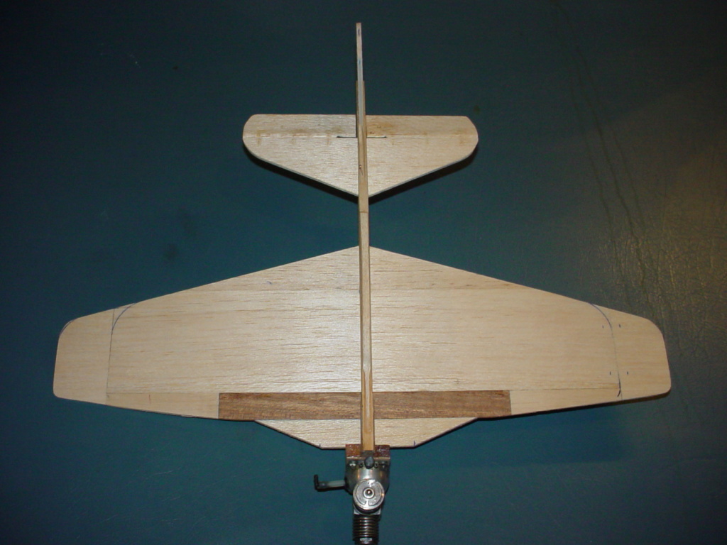
A sheet-balsa wing (alone..) would not be enough support for the upward shock of independent gear-struts on a less than graceful landing. I chose to build a 1/8" (3mm) thickness sheet-wing having a half-span hardwood "strip-spar" for two main gear-blocks to mount to.
Note the dark wood in the photo below.. I think it's Mahogany. It won't break..
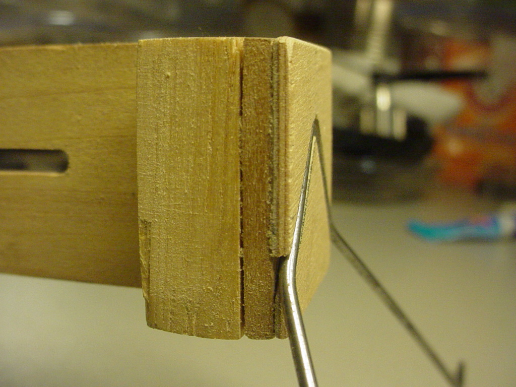
The independent struts were fabricated from .062" (1/16") music-wire and 3/8" square-hardwood (Cherry) blocks.
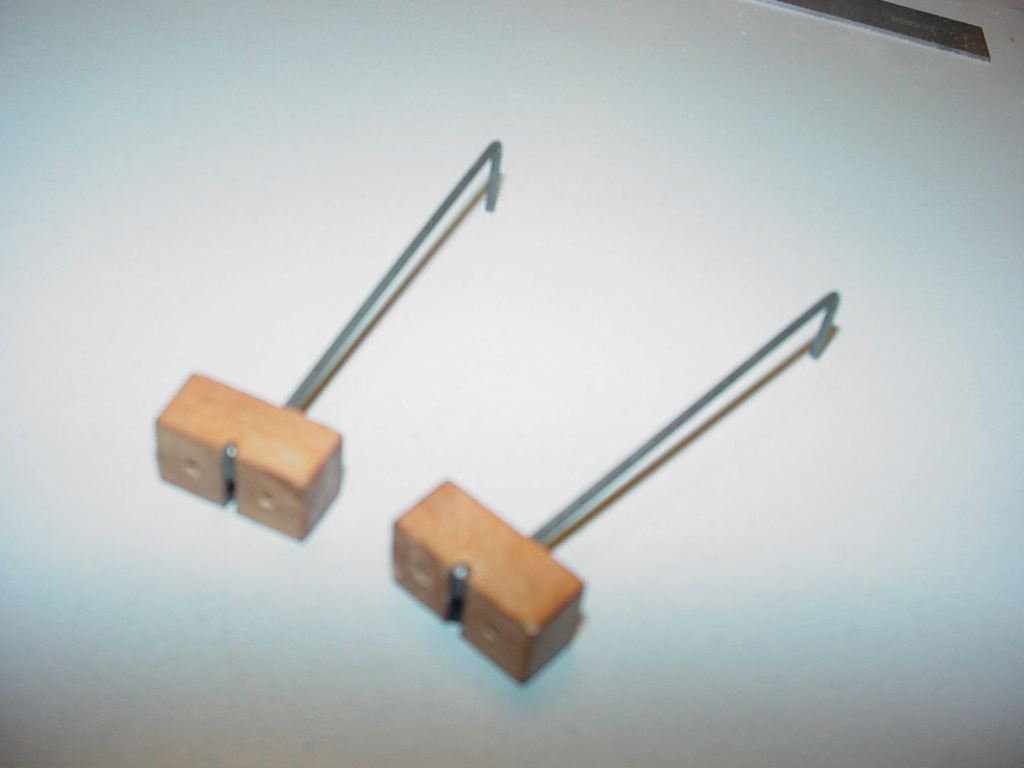
The assembly is RIGID. The Rare Bear has a 16" wingspan. The 1/8" (3mm) thickness Mahogany strip-spar is 8" long and 3/4" wide. The Cherry gear-blocks are 3/4" long.. and tie-into the strip-spar with #3 X 1/2"L. wood-screws.
This type of strut assy is made by drilling-through the gear-block to receive a straight-length of the strut-wire. The block is then "notched" to accept a short (1/4") L-bend (90 degrees) which is made in the strut-wire AFTER it is inserted through the block. The lower-strut's length is then measured, cut and bent 90 degrees to form the axle. This assembly is now captive. It's important to be accurate when measuring for the bends. We're making a "pair".. and they need to be the same length. The axle's length can vary slightly.. but if the o/a strut-lengths vary.. it will show-up on static-display.. and there's not much you can do to correct that after the fact. Yea.. it's a bit of fuss, but it makes for a more stout/scale-like main gear.. and if you're like "me".. you find this type of challenge enjoyable. Maybe it's because it's "smaller".. and takes more patience or ingenuity to design/build a particular component?
Here are the pair of strut-assemblies with simulated gear-doors made from clear plastic sheet..
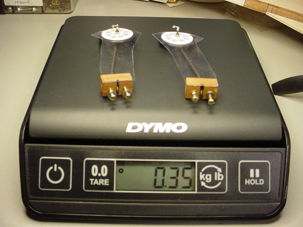
The hardwood strip-spar; I ripped a piece of 3/4" (19mm) hardwood to the same thickness of my sheet-balsa wing.. and butt-jointed together with CA. The strip is approx. 1/2 the wingspan.. or 8". It's not terribly heavy for what it does.. and being designed as a speed-model; I wasn't terribly concerned with its overall weight.
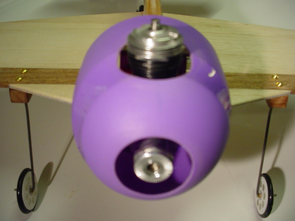
The gear-doors are simple to make. The wheel-collar locks them onto the lower-end.. and the upper section is fastened to the gear-block; trimming-out the entire strut assembly nicely.
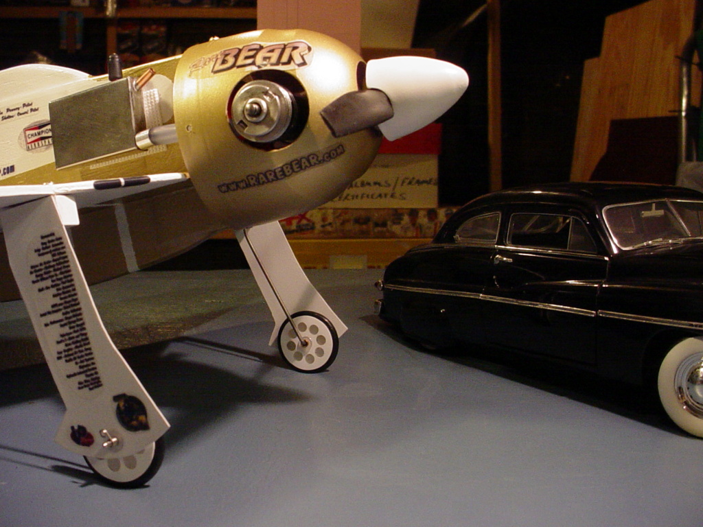
I have to admit that I enjoy the designing/fabricating/building-processes quite a bit. I wish I had the same patience.. when it comes to finish/painting..
There are pros and cons, as one can imagine. If a model is intended to launch by ROG (Rise off Ground) then a landing-gear is obviously required. If the model must land on pavement, then it will need an undercarriage to protect the airframe from shock and abrasion. These points I would call “pros”.
Another “pro” is being able to tweak the models’ center of gravity via wheel-weight.. which I would consider to be a functional advantage. The wire-struts can also be adjusted (bent) fore/aft providing additional c/g trimming.
Some “cons” might be the added weight and aerodynamic-drag induced to a model that was built for a certain purpose. A control-line combat model (often a flying-wing) wouldn’t have a landing-gear. Scratch-builders may elect to omit L/G, if none was specified or illustrated on a plan or drawing. Even “if” a gear is shown.. some people don’t want or feel the need to fabricate one. Keep in mind, that a tail-dragger gear-design in a scale-like location on a small model could cause nose-over crashes when taking-off or landing.. especially on a grass field.
Materials usually include music-wire for the strut(s) which must be formed (bent) with an overall length to account for a “mounting” to the model. A strut formation must be long enough (with a subject wheel-tire mounted) to provide adequate clearance for subject propeller(s) and have an axle; long enough to accept a wheel or ski and a retention collar. Wire diameter for “mains” on a 1/2A model is generally .047”/.062”. (1.2/1.6mm). Music wire in these sizes is relatively easy to source. K & S metals may still offer 36” lengths.. which is what I’ve bought. A single 12” length is generally enough material to form an inverted “V” gear for most half-A tail-draggers. A tail-skid can be as simple as a toothpick or sm. hardwood dowel.
I designed my 1st ever tri-cycle gear for a self-designed profile Lockheed T33 for the CEF 2017/18 Speed Contest. The wire is .062” dia. I used an inverted-“V” for the mains located approx. mid-chord in the fuses’ wing-slot and angled straight-down (90 degrees) The nosegear mount ties-into the lower beam engine-mount; is slightly longer than the mains.. and is angled slightly aft.. in an effort to dampen the shock of landing.


More recently I designed my 2nd half-A C/L model scratch-build of yet another Lockheed warbird; My profile P38 which I would design a different-style tricycle gear for. Its’ twin-booms/engine-nacelles required independent main-struts to provide for straight-ahead tracking.


Here’s how I did the P38’s nose-gear..


My very 1st experimentation with a scale-like tail-dragger gear-design was what I came up with for the 1st annual CEF profi-scale speed-contest, in my 16” span model of the Grumman F8F-2 Bearcat/Rare-Bear.
I wanted scale-like (independent) gear-struts.. UNLIKE the common "inverted V" that is often found WAY up-front on profile model kits.. or saddled in the fuse's wing-slot and strapped-against plywood nose doublers.
A sheet-balsa wing (alone..) would not be enough support for the upward shock of independent gear-struts on a less than graceful landing. I chose to build a 1/8" (3mm) thickness sheet-wing having a half-span hardwood "strip-spar" for two main gear-blocks to mount to.
Note the dark wood in the photo below.. I think it's Mahogany. It won't break..


The independent struts were fabricated from .062" (1/16") music-wire and 3/8" square-hardwood (Cherry) blocks.

The assembly is RIGID. The Rare Bear has a 16" wingspan. The 1/8" (3mm) thickness Mahogany strip-spar is 8" long and 3/4" wide. The Cherry gear-blocks are 3/4" long.. and tie-into the strip-spar with #3 X 1/2"L. wood-screws.
This type of strut assy is made by drilling-through the gear-block to receive a straight-length of the strut-wire. The block is then "notched" to accept a short (1/4") L-bend (90 degrees) which is made in the strut-wire AFTER it is inserted through the block. The lower-strut's length is then measured, cut and bent 90 degrees to form the axle. This assembly is now captive. It's important to be accurate when measuring for the bends. We're making a "pair".. and they need to be the same length. The axle's length can vary slightly.. but if the o/a strut-lengths vary.. it will show-up on static-display.. and there's not much you can do to correct that after the fact. Yea.. it's a bit of fuss, but it makes for a more stout/scale-like main gear.. and if you're like "me".. you find this type of challenge enjoyable. Maybe it's because it's "smaller".. and takes more patience or ingenuity to design/build a particular component?

Here are the pair of strut-assemblies with simulated gear-doors made from clear plastic sheet..

The hardwood strip-spar; I ripped a piece of 3/4" (19mm) hardwood to the same thickness of my sheet-balsa wing.. and butt-jointed together with CA. The strip is approx. 1/2 the wingspan.. or 8". It's not terribly heavy for what it does.. and being designed as a speed-model; I wasn't terribly concerned with its overall weight.

The gear-doors are simple to make. The wheel-collar locks them onto the lower-end.. and the upper section is fastened to the gear-block; trimming-out the entire strut assembly nicely.

I have to admit that I enjoy the designing/fabricating/building-processes quite a bit. I wish I had the same patience.. when it comes to finish/painting..
Last edited by roddie on Fri Mar 27, 2020 2:35 pm; edited 1 time in total
 Re: Landing-gear 1/2-A variations
Great tutorial roddie. Thanks for taking the time to do it.

NEW222- Top Poster

- Posts : 3896
Join date : 2011-08-13
Age : 46
Location : oakbank, mb
 Re: Landing-gear 1/2-A variations
I hadn't seen baking soda used for filler, does that work with C/A glue? Do you find the joint crumbly at all?

daddyo- Gold Member

- Posts : 139
Join date : 2012-11-26
Age : 56
Location : California
 Re: Landing-gear 1/2-A variations
NEW222 wrote:Great tutorial roddie. Thanks for taking the time to do it.
Thank you Chancey, It's a pleasure for me to share some of my methods here.
 Re: Landing-gear 1/2-A variations
daddyo wrote:I hadn't seen baking soda used for filler, does that work with C/A glue? Do you find the joint crumbly at all?
I haven't used baking soda as a filler. Sometimes I use baking-soda as an "accelerator" for the C/A glue. Occasionally a C/A glue-joint won't "set". Sprinkling a "pinch" of baking soda over the problem-area usually helps. I believe it has something to do with the two surfaces' to be joined; pH levels. This can also happen when joining dissimilar materials with C/A glue.
Be careful not to use too much of either; C/A or baking soda in areas where a smooth-finish is wanted. IT DOESN'T SAND WELL.. and on balsa.. this can be disastrous.
There are small pump-spray bottles containing a "liquid" accelerator for C/A glues.. usually sold by the hobby-grade C/A manufacturers such as "ZAP". It's sometimes called "Kicker". When a C/A glue-joint sets/grabs.. it's commonly referred to as "kicking".
 Re: Landing-gear 1/2-A variations
I've found lightweight synthetic spackling putty or paste sold in home improvement stores and sections in department stores works well to repair imperfections in balsa and foam, dries reasonably quick, is easy to sand.

GallopingGhostler- Top Poster


Posts : 5724
Join date : 2013-07-13
Age : 70
Location : Clovis NM or NFL KC Chiefs
 Similar topics
» Landing Gear or Protection Skid
» The CEF Reed Speed Contest… a very late entry
» P-38 Lightning-Roddie style..
» Need an Aeromite landing gear
» Stick built rubber powered Scientific ME-109
» The CEF Reed Speed Contest… a very late entry
» P-38 Lightning-Roddie style..
» Need an Aeromite landing gear
» Stick built rubber powered Scientific ME-109
Page 1 of 1
Permissions in this forum:
You cannot reply to topics in this forum

 Rules
Rules


