Log in
Search
Latest topics
» Purchased the last of any bult engines from Ken Enyaby Coxfledgling Today at 4:18 am
» My N-1R build log
by roddie Today at 12:32 am
» Happy 77th birthday Andrew!
by akjgardner Today at 12:27 am
» TEE DEE Having issues
by TD ABUSER Yesterday at 9:43 pm
» Landing-gear tips
by roddie Yesterday at 6:17 pm
» Roger Harris revisited
by TD ABUSER Yesterday at 2:13 pm
» Tee Dee .020 combat model
by Ken Cook Yesterday at 1:41 pm
» Retail price mark-up.. how much is enough?
by Ken Cook Yesterday at 1:37 pm
» My latest doodle...
by roddie Yesterday at 10:43 am
» Chocolate chip cookie dough.........
by roddie Fri Nov 22, 2024 1:13 pm
» Free Flight Radio Assist
by rdw777 Fri Nov 22, 2024 9:24 am
» Funny what you find when you go looking
by rsv1cox Wed Nov 20, 2024 3:21 pm
Cox Engine of The Month
"Flying Blind" a build-thread for CEF 2018 Speed
Page 1 of 2
Page 1 of 2 • 1, 2 
 "Flying Blind" a build-thread for CEF 2018 Speed
As mentioned in the latest contest-thread.. I found several of these thin wooden "slats" in the back of an old abandoned garage about five years ago. Being "me".. I salvaged them; thinking that I could use them in my model-shop. They were once part of a "window-blind".
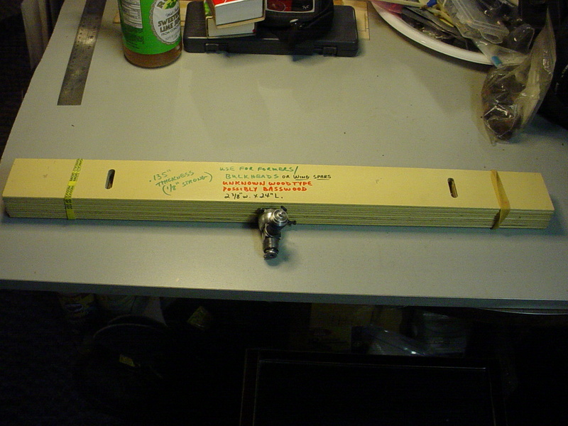
They're warp-free/perfectly flat.. and possibly made of basswood..?? Each slat measures .135" thick x 2.375" wide x 24.0" long. There are two "slots" 4.5" from each end on center; .281" wide x 1.187" long. These measurements were of importance to me.. because I intended to "plug" the two slots using a cut-off from one end of the piece.
I had previously mentioned using "only one" piece of this stock for the entire airframe of the model. I don't know if I can accomplish that.. but I needed to have a "void-free" piece of stock to work with.. so I set-out to cut plugs for the slots.
I used my miter-saw to cut-off an end-piece approx. .300" wide. I then used my razor-saw to cut the piece in half; yielding two pieces for the plugs.

These were then hand-sanded to fit the slots..
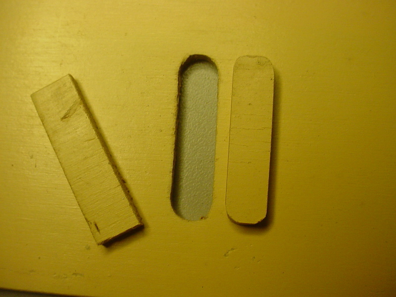
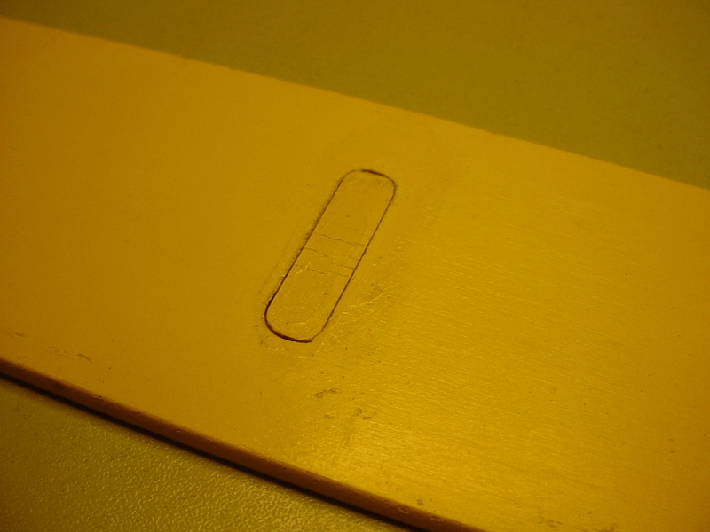
tapped-in with hammer and wood-block; I applied thin CA glue.. and wiped-over the joints using a small square of wax-paper.
These slats had been painted when I found them.. so I knew I would be sanding that finish off. I'd recently bought a new "Porter-Cable" brand 1/4-sheet electric sander for refinishing our front wooden steps.. and it had a decent sheet of abrasive already loaded.

After sanding; the piece now measures between .120"/.125" thick.. and I now have 56 "solid" square inches to work with.
Before plugging the slots.. I couldn't really lay-out a design. This is intended to be a "sheet/profile" model.. and the "open slots" were messing with my visualization. It was a bit tedious to plug them.. but it's done.. and I fitted them tightly. The two plugs were CA-glued on both sides of the sheet to assure penetration into the joint.
Now I can start to lay-out the "outlines". I have 2.375" max. of wing-chord.. which I figure is plenty. I'm going with a constant-chord wing. I'm undecided as to the span.. but I'm leaning toward 9-10". I may sweep the tips.. we'll see. The wing and stabilizer slots in the fuse will be cut using my Dremel-tool with router-attachment and 1/8" diameter tool. This will be done using a "fence" to assure that the two slots align with each other. I haven't figured a fuse-length/tail-moment yet.. but after I cut the wing.. I'll have between 13-14" of stock left to work with. Out of that leftover piece, I'll also need a stabilizer, elevator and fin.
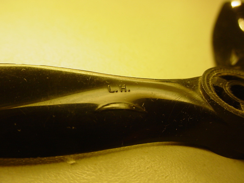
Let's discuss something more fun. I'll be running a reed-valve engine on this model. The propeller will be a left-hand 3-blade Cox part.

I intend to launch R.O.G./CCW with an inverted-"V" main-gear of stout 1/16" music wire with 3/4" dia. wooden wheels. I like 1/16" wire-gear for small airplanes.. because it's sturdy.. and will absorb a lot of shock. When the engine quits... these models drop like a rock. A stout gear angled well-forward will "take the hit" before the engine does. If you're flying over a hard-surface.. it can save your engine.
An inverted-V gear can also be mounted to a profile fuse; such as to allow fore/aft adjustment to help trim balance.

They're warp-free/perfectly flat.. and possibly made of basswood..?? Each slat measures .135" thick x 2.375" wide x 24.0" long. There are two "slots" 4.5" from each end on center; .281" wide x 1.187" long. These measurements were of importance to me.. because I intended to "plug" the two slots using a cut-off from one end of the piece.
I had previously mentioned using "only one" piece of this stock for the entire airframe of the model. I don't know if I can accomplish that.. but I needed to have a "void-free" piece of stock to work with.. so I set-out to cut plugs for the slots.
I used my miter-saw to cut-off an end-piece approx. .300" wide. I then used my razor-saw to cut the piece in half; yielding two pieces for the plugs.

These were then hand-sanded to fit the slots..

tapped-in with hammer and wood-block; I applied thin CA glue.. and wiped-over the joints using a small square of wax-paper.

These slats had been painted when I found them.. so I knew I would be sanding that finish off. I'd recently bought a new "Porter-Cable" brand 1/4-sheet electric sander for refinishing our front wooden steps.. and it had a decent sheet of abrasive already loaded.

After sanding; the piece now measures between .120"/.125" thick.. and I now have 56 "solid" square inches to work with.
Before plugging the slots.. I couldn't really lay-out a design. This is intended to be a "sheet/profile" model.. and the "open slots" were messing with my visualization. It was a bit tedious to plug them.. but it's done.. and I fitted them tightly. The two plugs were CA-glued on both sides of the sheet to assure penetration into the joint.
Now I can start to lay-out the "outlines". I have 2.375" max. of wing-chord.. which I figure is plenty. I'm going with a constant-chord wing. I'm undecided as to the span.. but I'm leaning toward 9-10". I may sweep the tips.. we'll see. The wing and stabilizer slots in the fuse will be cut using my Dremel-tool with router-attachment and 1/8" diameter tool. This will be done using a "fence" to assure that the two slots align with each other. I haven't figured a fuse-length/tail-moment yet.. but after I cut the wing.. I'll have between 13-14" of stock left to work with. Out of that leftover piece, I'll also need a stabilizer, elevator and fin.
Let's discuss something more fun. I'll be running a reed-valve engine on this model. The propeller will be a left-hand 3-blade Cox part.


I intend to launch R.O.G./CCW with an inverted-"V" main-gear of stout 1/16" music wire with 3/4" dia. wooden wheels. I like 1/16" wire-gear for small airplanes.. because it's sturdy.. and will absorb a lot of shock. When the engine quits... these models drop like a rock. A stout gear angled well-forward will "take the hit" before the engine does. If you're flying over a hard-surface.. it can save your engine.
An inverted-V gear can also be mounted to a profile fuse; such as to allow fore/aft adjustment to help trim balance.
 Re: "Flying Blind" a build-thread for CEF 2018 Speed
Oh my,my you punster you. Took two readings to catch the “flying blind” reference. double meaning got a good belly laugh.

Marleysky- Top Poster


Posts : 3618
Join date : 2014-09-28
Age : 72
Location : Grand Rapids, MI
 Re: "Flying Blind" a build-thread for CEF 2018 Speed
Marleysky wrote:Oh my,my you punster you. Took two readings to catch the “flying blind” reference. double meaning got a good belly laugh.

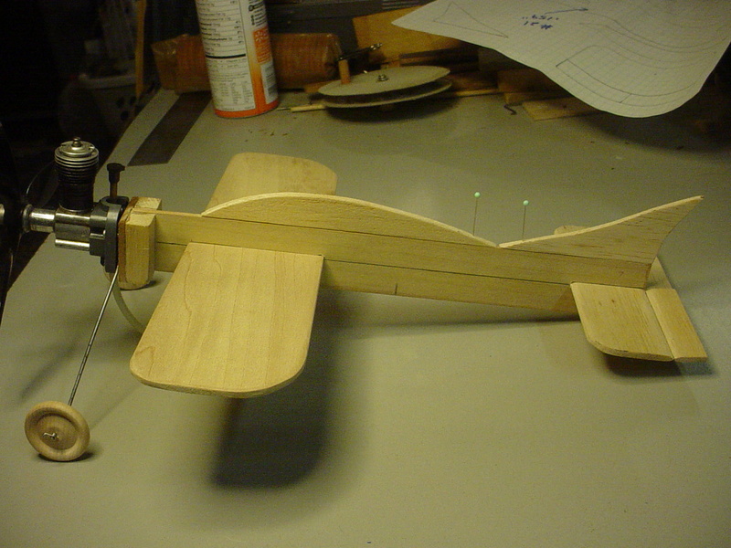
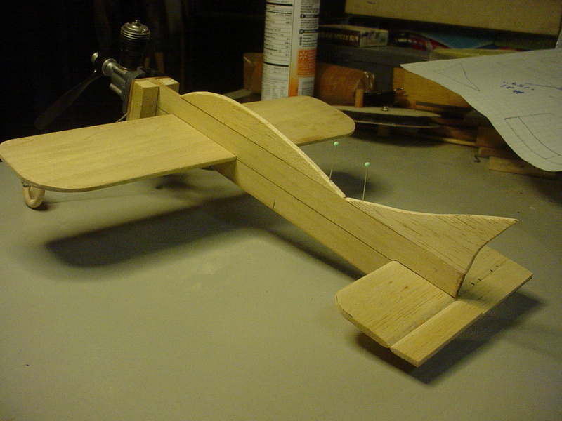
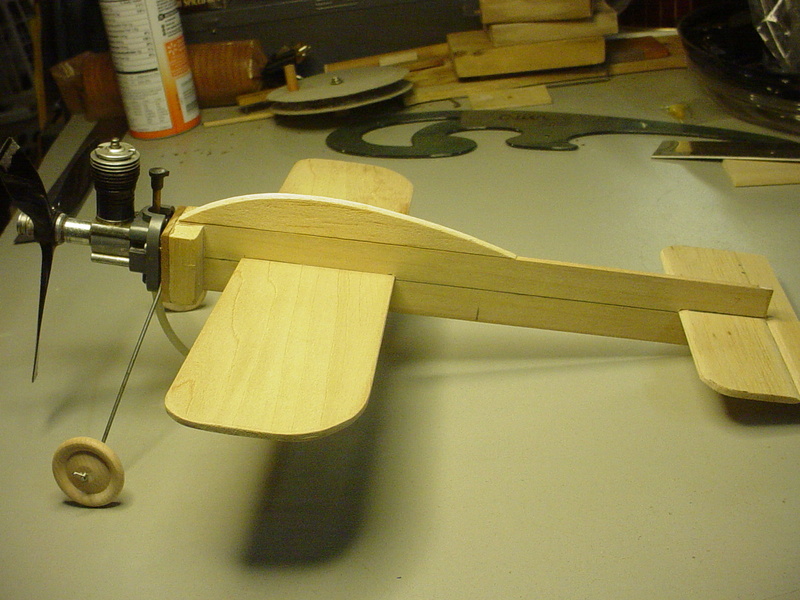
You might recognize some pieces that will make-up an airplane. I cut a "wing-blank" from the sheet-stock to establish the root-chord.. then cut a "fuse-blank" in order to cut a wing-slot. I had planned to "rout" the wing-slot.. but a set-up jig was more than my brain could process. I laid-out the slot and drilled two 1/8" holes at the opposing-ends for cutting-out the slot with a razor-knife. A little sanding using an emery-board.. and the wing-panel fits nicely into the slot.
Tonight I'm working on the engine-mount. I've decided to make the L/G gear wire integral to it. This I feel will simplify the design.. as well as locate the gear-struts "forward" to help protect the engine.

Kim- Top Poster


Posts : 8625
Join date : 2011-09-06
Location : South East Missouri
 just a few moments..
In my designing and "your" looking at this... keep in mind that I'm just establishing some "moments" that I think might work. I designed my Rare Bear in the same way.

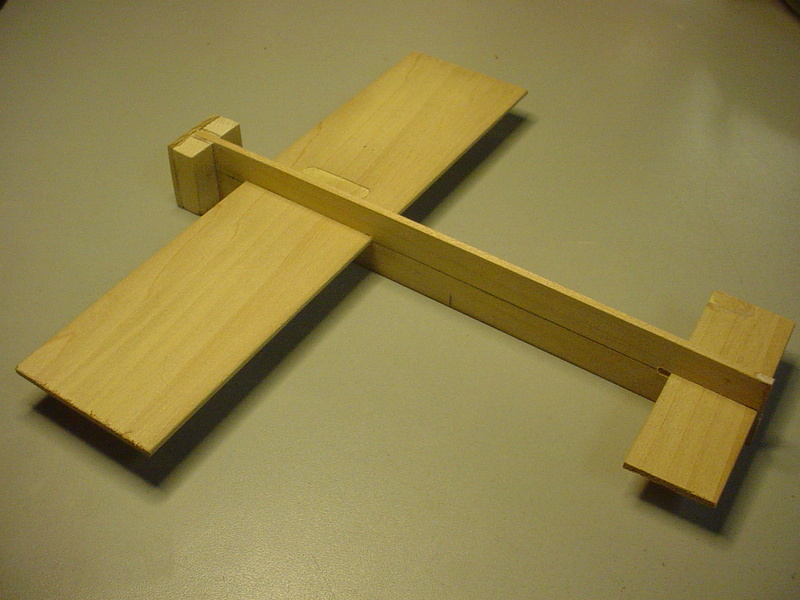
This wood is not balsa. I think it's Basswood.. but it's quite rigid. I will use some balsawood.. but I wanted a rigid forward-structure to build on.
The "nose" is my usual construction for a radial-mounted engine. I like to use vertical hardwood blocks behind the firewall-plate.. in case we get "punched hard in the nose"... On this model however; I'm looking to install four balsawood "cheeks" faired aerodynamically back into the wing. I don't usually do that.. but I really should on this model.
I "sculpt" as I build.. and will add lightweight balsa contours to the fuse.. such as a canopy and fin that compliments the vertical stabilizer and rudder. The fuselages' belly will support a "capsule" for a balloon-style fuel supply.
The reed-valve engine will be configured as a product-engine.. with horseshoe-style backplate/carb oriented "vertically" with upright cylinder/needle-valve assy. The main landing-gear wire will be an "inverted-V" made from .062" piano-wire, sandwiched between the engines' backplate and the models' firewall; angled several degrees forward to provide some shock-absorbing on landing to protect the engine.
I'm stalled a bit on how to design the stab./elevator. They obviously must be "hinged" to control the models' pitch. If I use the hardwood-stock, it will be challenging to hinge the two pieces in the way of which I'm accustomed. The "tail-section" is least likely to damaged in a hard-landing. Still; I've marveled at the "stitched-hinge" technique which could be applied; should I decide to use hardwood panels.
I always "over-think" my designs... it's a curse..,.


This wood is not balsa. I think it's Basswood.. but it's quite rigid. I will use some balsawood.. but I wanted a rigid forward-structure to build on.
The "nose" is my usual construction for a radial-mounted engine. I like to use vertical hardwood blocks behind the firewall-plate.. in case we get "punched hard in the nose"...
I "sculpt" as I build.. and will add lightweight balsa contours to the fuse.. such as a canopy and fin that compliments the vertical stabilizer and rudder. The fuselages' belly will support a "capsule" for a balloon-style fuel supply.
The reed-valve engine will be configured as a product-engine.. with horseshoe-style backplate/carb oriented "vertically" with upright cylinder/needle-valve assy. The main landing-gear wire will be an "inverted-V" made from .062" piano-wire, sandwiched between the engines' backplate and the models' firewall; angled several degrees forward to provide some shock-absorbing on landing to protect the engine.
I'm stalled a bit on how to design the stab./elevator. They obviously must be "hinged" to control the models' pitch. If I use the hardwood-stock, it will be challenging to hinge the two pieces in the way of which I'm accustomed. The "tail-section" is least likely to damaged in a hard-landing. Still; I've marveled at the "stitched-hinge" technique which could be applied; should I decide to use hardwood panels.
I always "over-think" my designs... it's a curse..,.
 main-gear fabricated
I had a scrap-piece of .062" piano-wire that turned-out to be long-enough to bend-up for a my main-gear.  I trimmed it to approx. 8" long. I bent it 90 degrees at the halfway-point.. and then bent the axles 45 degrees for my 1" diameter wheels.
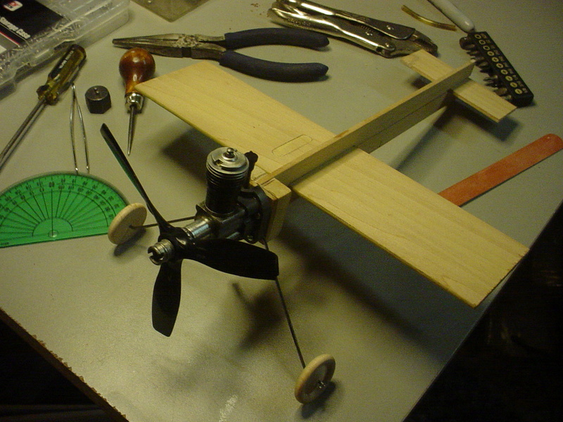
This will provide 1/2" clearance for the propeller when the fuselage levels-out on launch.

This will provide 1/2" clearance for the propeller when the fuselage levels-out on launch.
 Re: "Flying Blind" a build-thread for CEF 2018 Speed
The Racer is coming along Nicely Roddie good to see your going to the races with it ! 


getback- Top Poster


Posts : 10442
Join date : 2013-01-18
Age : 67
Location : julian , NC
 Re: "Flying Blind" a build-thread for CEF 2018 Speed
getback wrote:The Racer is coming along Nicely Roddie good to see your going to the races with it !
Hey thanks buddy! I hope that you build something. Just use your imagination. No scale requirement this time around!
I used my usual hinging-method on my elevator-panel to cut slots for CA hinges..
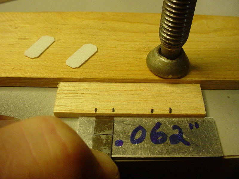
That's an X-acto narrow chisel blade, held flat atop a spacer which is half the thickness of my work-piece. I mark the blade for a set-depth. Rocking the blade from side to side while applying slight inward pressure, cuts a nice slot quite easily.
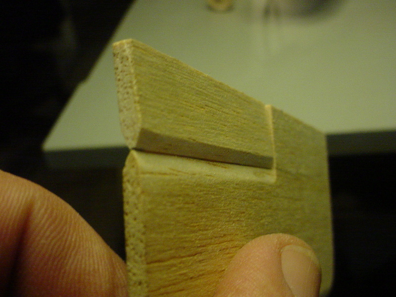
I used a French-curve to draw a couple different canopies.

The longer one looks kinda' cool.. but I'll probably end up using the shorter one. It's amazing how repositioning a canopy fore/aft can really change the whole look.



That's an X-acto narrow chisel blade, held flat atop a spacer which is half the thickness of my work-piece. I mark the blade for a set-depth. Rocking the blade from side to side while applying slight inward pressure, cuts a nice slot quite easily.

I used a French-curve to draw a couple different canopies.

The longer one looks kinda' cool.. but I'll probably end up using the shorter one. It's amazing how repositioning a canopy fore/aft can really change the whole look.


 Re: "Flying Blind" a build-thread for CEF 2018 Speed
Looking Good Roddie, Nice job on the elevator.

akjgardner- Diamond Member


Posts : 1602
Join date : 2014-12-28
Age : 65
Location : Greensberg Indiana
 Re: "Flying Blind" a build-thread for CEF 2018 Speed
Roddie, that's a cool looking design! Speed planes often seem to have their wings made of something a bit harder than balsa. Seeing your model reminded me of the "Santana" by Dale Kirn, it has poplar wings:
http://www.outerzone.co.uk/plan_details.asp?ID=7961
http://www.outerzone.co.uk/plan_details.asp?ID=7961

KariFS- Diamond Member

- Posts : 2044
Join date : 2014-10-10
Age : 53
 Re: "Flying Blind" a build-thread for CEF 2018 Speed
KariFS wrote:Roddie, that's a cool looking design! Speed planes often seem to have their wings made of something a bit harder than balsa. Seeing your model reminded me of the "Santana" by Dale Kirn, it has poplar wings:
http://www.outerzone.co.uk/plan_details.asp?ID=7961
Thanks Kari! I'm not sure what this wood is. I guess it could be poplar.. but its color is different than most poplar that I've seen. The elevator, canopy and fin are balsa. I still may trace the canopy and fin onto the leftover blind-stock. I would have used the blind-stock for the elevator if I went with a stitched-hinge, but I opted for the CA hinges which would have been tough to slot in harder wood. I need to get some functional weight rearward. A beefy piano-wire control-rod will help some.. along with a tail-skid/wheel.
There's still lots to work-out. I was going to mount a belly-tank (balloon-style).. but I'm concerned about there not being enough suction to pull fuel. The rules state a "suction-only" fuel-feed. It's just as well.. because I have no experience with pressure-bladders.
 Re: "Flying Blind" a build-thread for CEF 2018 Speed

MauricioB- Top Poster

- Posts : 3712
Join date : 2016-02-16
Age : 53
Location : ARG
 Re: "Flying Blind" a build-thread for CEF 2018 Speed
MauricioB wrote:
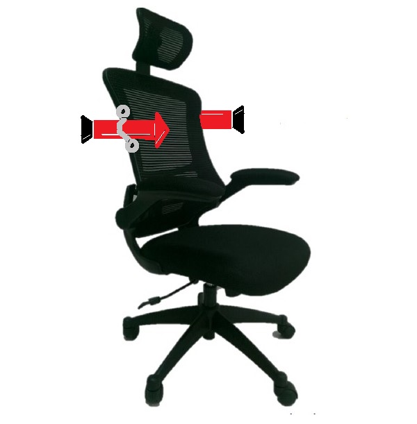
that will be a "bullet" spinning around you !!, you're going to need a rotating chair Roddie !!!
..... I could not there!

Ha Ha!
 Re: "Flying Blind" a build-thread for CEF 2018 Speed
The rudder shape feels out of place but doesn't look bad - everything else has a round corner.
Everything looks good in fact.
Phil
Everything looks good in fact.
Phil

pkrankow- Top Poster

- Posts : 3025
Join date : 2012-10-02
Location : Ohio
 Re: "Flying Blind" a build-thread for CEF 2018 Speed
I'm following this thread roddie.
Looks like you have the wings balance position solidly fixed. How did you figure the tail moment, higher math or Kelly Johnson's "cut and try" method. (My favorite )
)
I love the flowing canopy, not so much the vertical stab. I'm with Phil on that one.
Interesting using old blinds for material. It's got me casting around for some. I have some poplar stock, keep it for bearers etc. Keep up the excellent work.
Bob
Looks like you have the wings balance position solidly fixed. How did you figure the tail moment, higher math or Kelly Johnson's "cut and try" method. (My favorite
I love the flowing canopy, not so much the vertical stab. I'm with Phil on that one.
Interesting using old blinds for material. It's got me casting around for some. I have some poplar stock, keep it for bearers etc. Keep up the excellent work.
Bob

rsv1cox- Top Poster


Posts : 11250
Join date : 2014-08-18
Location : West Virginia
 Re: "Flying Blind" a build-thread for CEF 2018 Speed
rsv1cox wrote:I'm following this thread roddie.
Looks like you have the wings balance position solidly fixed. How did you figure the tail moment, higher math or Kelly Johnson's "cut and try" method. (My favorite)
I love the flowing canopy, not so much the vertical stab. I'm with Phil on that one.
Interesting using old blinds for material. It's got me casting around for some. I have some poplar stock, keep it for bearers etc. Keep up the excellent work.
Bob
Nothing is "fixed".. my life is a mess...
This model has a 9.5" wingspan.. and approx. 22" sq. in. area. I felt that a longer tail-moment would help to keep the model "stabilized/level" while in flight.
The split-elevator for instance. The drawings I've seen of "speed-models" depict an inboard control-surface for CCW flight. I built/hinged my elevator with this in mind. I'm not sure "why".. but I hope that it's going to help to control this model. I'm really not sure; whereas the planned-propeller is a L/H one. I'm going with a L/H propeller because the torque-twist of the engine will roll the airplane "away" from center-circle. This may be inhibit maximum-speed a bit.. but could assist in launching with tighter-lines. I honestly don't know how my inboard split-elevator will affect the flight of the model.
As for the "fin/rudder"..... I'm not settled on that yet. I like the shape.. but it's just a mock-up at this point. It's one of the few balsa parts. I'd rather it be hardwood. Maybe a "sharp-wedge" with no radius-cuts?? It would stand-up better in a flip-over at launch.
 Re: "Flying Blind" a build-thread for CEF 2018 Speed
I love this thread and am watching\reading most eagerly.
Phil
Phil


chevyiron420- Gold Member

- Posts : 251
Join date : 2015-01-28
Age : 66
Location : Barney Georgia
 Re: "Flying Blind" a build-thread for CEF 2018 Speed
Of the few scratch builts I have done I always worried about the balance point first. Didn't matter at all with my P-38 as I built that to exact scale and didn't give a care as to balance. I hung two Golden Bees on it and amazingly the balance point turned out perfectly.
But you are building yours as a "speed" model and different animal. I have no experience with them but I would think the flat non-airfoil wing would be the fashion for that type of flight. I did get a speed pan and wing in a bundle buy once and promptly sent it to a member here as I had no desire to get into something that would no doubt aggravate my tendency to get dizzy and fall down.
I wouldn't think that you have tested a balance point yet as you have no fuel tank installed. The position of which could be varied to attain proper balance, but I have no idea if balance is most important in a speed model.
Looking forward to getting educated.
Bob

rsv1cox- Top Poster


Posts : 11250
Join date : 2014-08-18
Location : West Virginia

Kim- Top Poster


Posts : 8625
Join date : 2011-09-06
Location : South East Missouri

MauricioB- Top Poster

- Posts : 3712
Join date : 2016-02-16
Age : 53
Location : ARG
 controls..
What better thing to do on a Thanksgiving day.. than to work on a model airplane? Lynne was been busy in the kitchen.. and swatted me away like a fly.. so I stayed clear of all culinary work. 
 mmmMMMM!!! My girl can COOK!
Anyway.. I kept myself busy tinkering downstairs in my model shop all afternoon. Reamed-out some prop-hubs.. flushed-out some NVA's.. (Wen-Mac/Testors prep.) and then started working on a control-linkage for my current speed model.
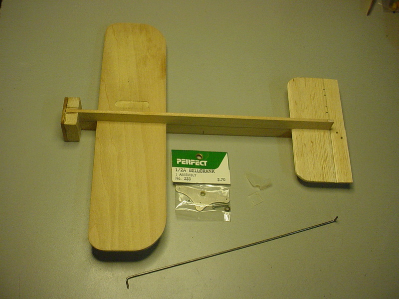
I had a short remnant-piece of .062" music-wire on my table, which turned-out to be the perfect length for the pushrod. This is good.. because the airplane needs some tail-weight BADLY. I formed two "L-bends" on the opposing ends, at 90 degrees to each other. The pushrod-length will locate the bell-crank assembly at mid-wing chord. Its pivot-hole will be drilled with the pushrod installed on the elevator-horn and also on the bell-crank. I will use the spring-type wheel-retainers to secure the linkage on both ends. The bell-crank is a "Perfect" brand #233 and the elevator-horn is a "Dubro" #107. The Dubro horn needs no mod for the .062" pushrod.. but the bell-crank's rod-holes needed to be drilled larger.
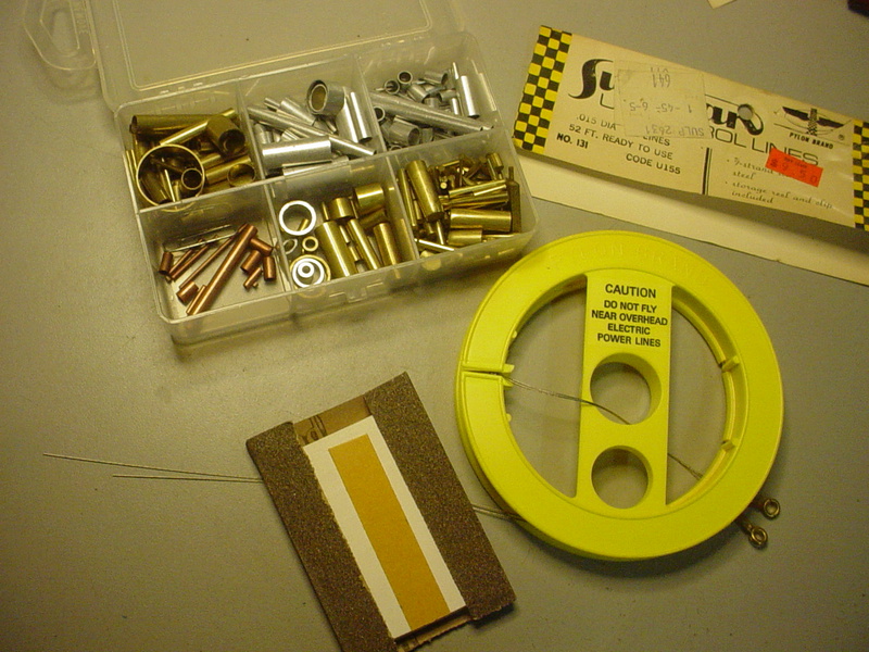
I'm using .015" 7-strand stainless cable for my lead-out wires.

Today I need to figure out a better solution for retaining the nose-gear.. .. The .062" inverted-V wire gear will be "sandwiched" between the firewall and the engine's back-plate. There needs to be some material in-between, to prevent distorting the back-plate when its mounting screws are tightened. I may have to cut and "piece-in" some 1/16" plywood around the wire, to provide a "flat" surface for mounting the engine. This will also prevent the gear from slipping "upward" when landing. I should have done this BEFORE I drilled the engine-mount holes. It's an even bigger issue now.. because I re-drilled those holes when I decided to change to a horizontally mounted backplate..
  I'm going to have to use a pin-vise and chase-drill from the "backside" of the firewall afterward, to avoid having to blind-drill a 3rd set of holes. It's more work than I wanted to do.. but it's the only way to do it at this point.
stay tuned..
 mmmMMMM!!! My girl can COOK!
 Anyway.. I kept myself busy tinkering downstairs in my model shop all afternoon. Reamed-out some prop-hubs.. flushed-out some NVA's.. (Wen-Mac/Testors prep.) and then started working on a control-linkage for my current speed model.
I had a short remnant-piece of .062" music-wire on my table, which turned-out to be the perfect length for the pushrod. This is good.. because the airplane needs some tail-weight BADLY. I formed two "L-bends" on the opposing ends, at 90 degrees to each other. The pushrod-length will locate the bell-crank assembly at mid-wing chord. Its pivot-hole will be drilled with the pushrod installed on the elevator-horn and also on the bell-crank. I will use the spring-type wheel-retainers to secure the linkage on both ends. The bell-crank is a "Perfect" brand #233 and the elevator-horn is a "Dubro" #107. The Dubro horn needs no mod for the .062" pushrod.. but the bell-crank's rod-holes needed to be drilled larger.

I'm using .015" 7-strand stainless cable for my lead-out wires.


Today I need to figure out a better solution for retaining the nose-gear..
 .. The .062" inverted-V wire gear will be "sandwiched" between the firewall and the engine's back-plate. There needs to be some material in-between, to prevent distorting the back-plate when its mounting screws are tightened. I may have to cut and "piece-in" some 1/16" plywood around the wire, to provide a "flat" surface for mounting the engine. This will also prevent the gear from slipping "upward" when landing. I should have done this BEFORE I drilled the engine-mount holes. It's an even bigger issue now.. because I re-drilled those holes when I decided to change to a horizontally mounted backplate..
 stay tuned..

 nose-gear mount
Not too tough a job.. but I'm glad that I have a scroll-saw.. 
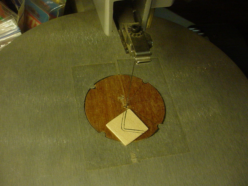
This will work..
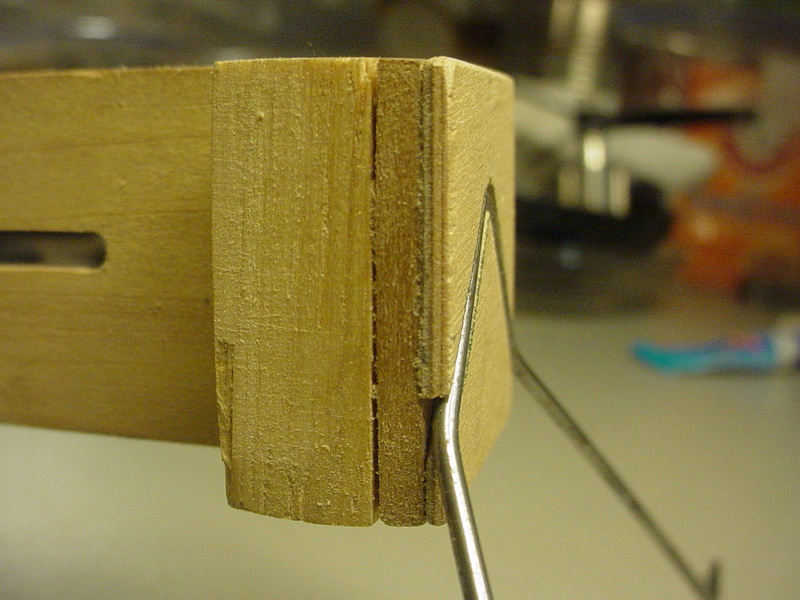
A pin-vise is indispensable for jobs such as this. I had drilled the holes through from the front-side, prior to gluing-on the gear-plates.


Just because this is a tiny model that might not even be able to fly.. doesn't mean that it doesn't deserve a little extra effort. Besides; it's the designing/building element that's my favorite part!
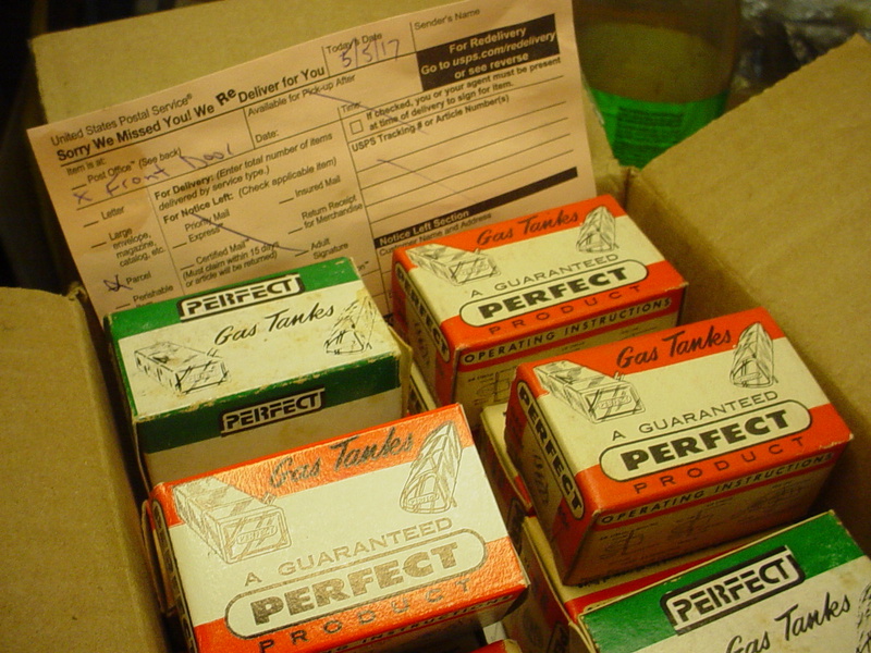
Hmmm.. what should I do next? I guess that I should pick-out a wedge-tank from the box-O-tanks that Dan McEntee sent me, back in May.
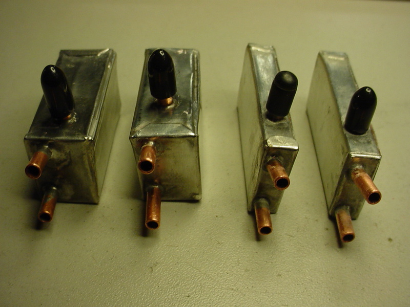
Not what I originally intended.. but I decided to go with a hard-tank rather than a balloon. I could also try one of the uni-flow tanks that I built for the "Rare Bear" three years ago.. man how the time fly's.. I can only hope that this airplane fly's as fast!

This will work..

A pin-vise is indispensable for jobs such as this. I had drilled the holes through from the front-side, prior to gluing-on the gear-plates.


Just because this is a tiny model that might not even be able to fly.. doesn't mean that it doesn't deserve a little extra effort. Besides; it's the designing/building element that's my favorite part!
Hmmm..
 what should I do next? I guess that I should pick-out a wedge-tank from the box-O-tanks that Dan McEntee sent me, back in May.
Not what I originally intended.. but I decided to go with a hard-tank rather than a balloon. I could also try one of the uni-flow tanks that I built for the "Rare Bear" three years ago.. man how the time fly's..

Page 1 of 2 • 1, 2 
 Similar topics
» Mike's Reed Speed 2 Bearcat build thread...
» Cox Engine Forum Speed Contest 2018!!!
» SIG Wonder build thread - ASP12 vs COX TD09
» Dragonfly Build Thread
» Anyone have plans for the Blink?
» Cox Engine Forum Speed Contest 2018!!!
» SIG Wonder build thread - ASP12 vs COX TD09
» Dragonfly Build Thread
» Anyone have plans for the Blink?
Page 1 of 2
Permissions in this forum:
You cannot reply to topics in this forum

 Rules
Rules

