Log in
Search
Latest topics
» My N-1R build logby roddie Today at 12:32 am
» Happy 77th birthday Andrew!
by akjgardner Today at 12:27 am
» TEE DEE Having issues
by TD ABUSER Yesterday at 9:43 pm
» Landing-gear tips
by roddie Yesterday at 6:17 pm
» Roger Harris revisited
by TD ABUSER Yesterday at 2:13 pm
» Tee Dee .020 combat model
by Ken Cook Yesterday at 1:41 pm
» Retail price mark-up.. how much is enough?
by Ken Cook Yesterday at 1:37 pm
» My latest doodle...
by roddie Yesterday at 10:43 am
» Chocolate chip cookie dough.........
by roddie Fri Nov 22, 2024 1:13 pm
» Purchased the last of any bult engines from Ken Enya
by sosam117 Fri Nov 22, 2024 11:32 am
» Free Flight Radio Assist
by rdw777 Fri Nov 22, 2024 9:24 am
» Funny what you find when you go looking
by rsv1cox Wed Nov 20, 2024 3:21 pm
Cox Engine of The Month
OK, Engine Gurus -- here's a question
Page 1 of 1
 OK, Engine Gurus -- here's a question
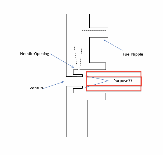
I've been cleaning up an older .049 (C-clipped piston) for a club member. I've seen this before, but never have had a good explanation for the design. In the backplate venturi, tank side, there is a thin circular protrusion with an ID the same as the venturi opening on the back. It extends about 1/4 of the distance into the venturi body on the front of the backplate. The venturi tube on the tank mates with venturi body, but does not extend far enough into the body to contact this protrusion. I normally use 25 gauge magnet wire with the enamel removed to clear and clean the needle seat. When the wire passes thru the needle seat, it hits this protrusion. I've wondered if it's there to improve vaporization, but it seems that it would have a tendency to reduce fuel draw since it blocks the needle hole from direct airflow.
So guys, anyone have an explanation for this since it looks to be there by design and not manufacturing flash.
I've attached a drawing (poorly done I'm afraid) of what I'm questioning. Imagine cutting a backplate in half directly down the center from top to bottom. The drawing is a cross section of what you would see with the protrusion labeled. If this post makes absolutely no sense, I'll try to provide clarification if possible.
andrew

 " />
" />
So guys, anyone have an explanation for this since it looks to be there by design and not manufacturing flash.
I've attached a drawing (poorly done I'm afraid) of what I'm questioning. Imagine cutting a backplate in half directly down the center from top to bottom. The drawing is a cross section of what you would see with the protrusion labeled. If this post makes absolutely no sense, I'll try to provide clarification if possible.
andrew
 " />
" /> Re: OK, Engine Gurus -- here's a question
Not sure but it could be a type of booster to increase fuel draw. (Bandit)

TDbandit- Platinum Member

- Posts : 897
Join date : 2014-12-01
Age : 53
Location : Riverdale Georgia
 Re: OK, Engine Gurus -- here's a question
Because the fuel doesn't spray directly into the airstream, perhaps it is designed to stop any blow-back of fuel out of the intake due to reed flutter. Just a thought.
Also, maybe it just helps to increase the pressure depression in the vicinity of the spray orifice.
Rod.
Also, maybe it just helps to increase the pressure depression in the vicinity of the spray orifice.
Rod.

Oldenginerod- Top Poster

- Posts : 4018
Join date : 2012-06-15
Age : 62
Location : Drouin, Victoria
 Re: OK, Engine Gurus -- here's a question
The drawing makes perfect sense, except that for my explanation/guess, I need to change some names. Lets call the hole in the backplate the "air intake," whereas the conical tube in the tank extending to the reed opening is the "venturi."
Maybe they were experimenting with keeping the intake air accelerated for a longer time before entering the venturi. Technically, in this odd case, that makes my so-called air inlet function as a venturi too. Maybe they hoped it would pull a stronger vacuum on the fuel inlet with less time to expand before entering the venturi nipple.
I wonder if you bored the backplate inlet to Black Widow size if it would take this flashing off.
Rusty
EDIT:
Yeah, that's about what I said. Rod beat me to it.Oldenginerod wrote:...Also, maybe it just helps to increase the pressure depression in the vicinity of the spray orifice.
Rod.
_________________
Don't Panic!
...and never Ever think about how good you are at something...
while you're doing it!
My Hot Rock & Blues Playlist
...and never Ever think about how good you are at something...
while you're doing it!
My Hot Rock & Blues Playlist

RknRusty- Rest In Peace

- Posts : 10869
Join date : 2011-08-10
Age : 68
Location : South Carolina, USA
 Re: OK, Engine Gurus -- here's a question
RknRusty wrote:
I wonder if you bored the backplate inlet to Black Widow size if it would take this flashing off.
Rusty
Rusty, to answer your question, yes, I think it would. I considered that, but because it wasn't my engine and it is an older model with the C-clip rod retainer, I'll leave it. I also considered coming in from the tank side with a larger bit and removing just the flashing (it's fairly thin) -- this would leave a slight chamfer on the inside of the air inlet and expose the fuel inlet to direct air flow. Fuel draw on most of our normally aspirated engines is due in part to manifold vacuum and partially to the venturi effect of accelerated air flow over the fuel orifice. The way the protrusion is positioned negates the venturi effect.
Maybe someone here has an engine disassembled with a metal backplate and can check to see if their backplate has the same design.
 Re: OK, Engine Gurus -- here's a question
I have a bunch of partial engines I can take a look at.
_________________
Don't Panic!
...and never Ever think about how good you are at something...
while you're doing it!
My Hot Rock & Blues Playlist
...and never Ever think about how good you are at something...
while you're doing it!
My Hot Rock & Blues Playlist

RknRusty- Rest In Peace

- Posts : 10869
Join date : 2011-08-10
Age : 68
Location : South Carolina, USA
 Re: OK, Engine Gurus -- here's a question
Bandit and Rod --
It may have been an experiment to increase fuel draw, but I don't understand how the physics would work in this case.
However, it could as Rod noted, reduce fuel blow back out the intake --- perhaps fuel remained in the cup formed by the venturi body and the protrusion. There is likely some positive pressure in the venturi tube either from reed flutter or from the reed simply re-seating during normal running.
 Re: OK, Engine Gurus -- here's a question
That very well could be it kinda would act like a type of "catch can" to reduce the spittle out the intake. (Bandit)andrew wrote:Bandit and Rod --
It may have been an experiment to increase fuel draw, but I don't understand how the physics would work in this case.
However, it could as Rod noted, reduce fuel blow back out the intake --- perhaps fuel remained in the cup formed by the venturi body and the protrusion. There is likely some positive pressure in the venturi tube either from reed flutter or from the reed simply re-seating during normal running.

TDbandit- Platinum Member

- Posts : 897
Join date : 2014-12-01
Age : 53
Location : Riverdale Georgia
 annular discharge
If your tank back plate does not have a screen you can see the reason for the design.
When the tank and back plate are mated together you will see a gap between the edge of the back plate hole and the end of the venturi. The fuel now has a 360 degree channel to atomize entering the venturi, hence the annular discharge concept. there is no needle or spray bar disrupting the air flow which is why the inlet is so much smaller than a sure start style back plate. Trying to enlarge the inlet too much will ruin it.
Mahalo
Agustin Jr.
When the tank and back plate are mated together you will see a gap between the edge of the back plate hole and the end of the venturi. The fuel now has a 360 degree channel to atomize entering the venturi, hence the annular discharge concept. there is no needle or spray bar disrupting the air flow which is why the inlet is so much smaller than a sure start style back plate. Trying to enlarge the inlet too much will ruin it.
Mahalo

Agustin Jr.

coxaddict- Gold Member

- Posts : 429
Join date : 2013-01-27
Location : north shore oahu, Hawaii
 Re: OK, Engine Gurus -- here's a question
I think I have seen this on metal backplates too, but haven't checked if it is there also on the plastic ones. I think the purpose is to create a primitive velocity stack and it is easier to see if you include the rest of the tank in the drawing.
The venturi effect relies on laminar flow, and you would not get a good fuel draw right after the intake aperture, where there is turbulent flow due to the sharp edge of the hole. Ideally the needle should be positioned much closer to the reed, but then the whole construction of the tank would be much more complicated.

The venturi effect relies on laminar flow, and you would not get a good fuel draw right after the intake aperture, where there is turbulent flow due to the sharp edge of the hole. Ideally the needle should be positioned much closer to the reed, but then the whole construction of the tank would be much more complicated.


Surfer_kris- Diamond Member

- Posts : 1912
Join date : 2010-11-20
Location : Sweden
 Re: OK, Engine Gurus -- here's a question
I guess the explanation is much less sophisticated than the difference between laminar and turbulent flow. With the protrusion/rim on the backplate the fuel leaving the needle valve orifice is more uniformly distributed around the intake tube perimeter and allows for a more efficient mixture with air. Without this cylindrical protrusion the intake tube would slurp in the fuel at its point nearest to the needle valve orifice, i.e not symmetrically.
Remember that the venturi body of the TD-s also includes 3 small holes on its perimeter to admit the fuel into the airflow in the most even way possible.
Remember that the venturi body of the TD-s also includes 3 small holes on its perimeter to admit the fuel into the airflow in the most even way possible.

balogh- Top Poster


Posts : 4958
Join date : 2011-11-06
Age : 66
Location : Budapest Hungary
 Re: OK, Engine Gurus -- here's a question
OK guys -- there have been a number of good explanations proposed. I'm going to play the Devil's Advocate --- not disagreeing with anyone, but just throwing out some more questions.
Rusty had asked earlier if the protrusion would be removed on the larger intake opening on the BW backplates. I suspected it might, but did not know for certain. I pulled a backplate from a stunt tanked BW this AM and it was gone.
Surfer Kris suggested that it could be a crude velocity stack. The has merit, but then fuel flow would be based on manifold vacuum only and not aided by the venturi or Bernoulli effect of increased air velocity over the fuel orifice. However, in support of Kris, the fuel inlet orifice on the BW is not in the direct path of air being pulled into the intake since the intake diameter is less than the shoulder diameter on the end of the tank venturi tube, so the orifice actually sits above the intake hole. There would be a lot of turbulent flow in the area, but I don't know if it would mitigate the Bernoulli effect. Because these engines were designed to run flat out and the BW was a better performer, the designers may have thought that the increased intake airflow on the BW did not need any additional boost.
I also wondered if the ring would improve vaporization. Balough made the same point and noted that the TDs use 3 fuel orifices on the NV ring. This protrusion is very small and fuel/air mix travels some distance down the venturi tube in the tank -- the tube is hot during normal running and there is a lot of turbulence when the fuel/air mixture passes around the reed, so I'm not sure that fuel mixing was part of this design.
Leroy Cox was a manufacturing genius with most of his production being done with screw machines. However, his castings were rough and had to be machined to final tolerances, unlike the injection molding today. I considered that the protrusion was perhaps drill or punch flash, but it's thickness and smooth edges tend to indicate that it was part of the machining process, so it seems that he had a function in mind.
The cylinder, BTW, is a single bypass cylinder without a boost flute.
 Re: OK, Engine Gurus -- here's a question
What about capillary action forming a continuous sprinkler ring?
I suspect that ring is in the right gap range to rather actively move fuel.
Phil
I suspect that ring is in the right gap range to rather actively move fuel.
Phil

pkrankow- Top Poster

- Posts : 3025
Join date : 2012-10-02
Location : Ohio
 Re: OK, Engine Gurus -- here's a question
andrew wrote:OK guys -- there have been a number of good explanations proposed. I'm going to play the Devil's Advocate --- not disagreeing with anyone, but just throwing out some more questions.
.....................I also wondered if the ring would improve vaporization. Balough made the same point and noted that the TDs use 3 fuel orifices on the NV ring. This protrusion is very small and fuel/air mix travels some distance down the venturi tube in the tank -- the tube is hot during normal running and there is a lot of turbulence when the fuel/air mixture passes around the reed, so I'm not sure that fuel mixing was part of this design........................
My comments:
1. The protrusion is short and the gap between the protrusion and the venturi tube is even shorter. Hence the fuel will fill the space around the rim and thus will enter the venturi along its full perimeter, helping the efficient mixing in the airflow. In reedy engines the high-frequency throbbing/vibration of the of the reed will further enhance vaporization.
2. The fuel-air mix travels much longer in a TD than in a tanked Bee (length of venturi plus that of the crankshaft, which is spinning fast, and is really-really hot, hence maximizing mixing and vaporization) still the design of the venturi includes 3 holes spaced equally around its perimeter to help improve the mixture of fuel and air...
So I still believe the impact of centrally symmetrical admission of the fuel into the airflow (with the rim in the BB backplate shown above, and with the 3 holes in the TD) on maximizing the fuel-air mixing should not be played down.

balogh- Top Poster


Posts : 4958
Join date : 2011-11-06
Age : 66
Location : Budapest Hungary
 Re: OK, Engine Gurus -- here's a question
andrew wrote:
Rusty had asked earlier if the protrusion would be removed on the larger intake opening on the BW backplates. I suspected it might, but did not know for certain. I pulled a backplate from a stunt tanked BW this AM and it was gone.
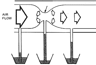
There are two effects that will give you a lower pressure, one is a venturi effect (from gas flow speed alone) and the other is a real pressure difference that gives the flow of gas in the first place (this is from the "suction" of the engine).
Using both gives you the best fuel draw, but using only the effect from a restriction is perfectly alright too. See the illustration below.
In a "typical" CL engine the spray-bar crosses the whole intake tube and there is one fuel-jet hole facing straight down the intake tube. This will only use one of the two effects (the "vacuum" or "suction" one), you get a better fuel draw from a hole which is slightly off center in the spray bar, as there you also have laminar flow and a venturi effect. This is utilized in PAW engines (two holes in the spray-bar, none facing straight down) and Super Tigre engines (rotatable spray-bar for midrange adjustment of the RC carb).

Surfer_kris- Diamond Member

- Posts : 1912
Join date : 2010-11-20
Location : Sweden
 Re: OK, Engine Gurus -- here's a question
Kris, I believe apart from the normal depression created by the suction of the engine, the Bernoulli effect may also have a boosting effect on the fuel draw in engines where the spraybar is crossing the air-intake: air will accelerate in the air-intake where part of the free-flow section is redued by the spraybar. Hence the higher air velocity in the spraybar area will reduce the static pressure of the air and add to the suction effect of the engine in drawing the fuel.

balogh- Top Poster


Posts : 4958
Join date : 2011-11-06
Age : 66
Location : Budapest Hungary
 Re: OK, Engine Gurus -- here's a question
The venturi effect is described by Bernoulli's principle (or equation), so they are one and the same effect. It only works for ideal, non-turbulent, flow.
In the wake of a regular spray-bar there will be turbulent flow, so the lowest pressure point is slightly off-set from straight down the venturi, where there is still some laminar flow.
I believe this is also used on the Medallion engines, but it has been a while since I had one appart, the hole in the spray cannot (or shouldn't at least) be mounted straight down.

Last edited by Surfer_kris on Mon Jan 05, 2015 3:53 am; edited 2 times in total

Surfer_kris- Diamond Member

- Posts : 1912
Join date : 2010-11-20
Location : Sweden
 Re: OK, Engine Gurus -- here's a question
There is a good discussion about Venturi's (and many other things) here; http://www.clacro.de/
(click on design in the left menu, then Venturi)

(click on design in the left menu, then Venturi)


Surfer_kris- Diamond Member

- Posts : 1912
Join date : 2010-11-20
Location : Sweden
 Re: OK, Engine Gurus -- here's a question
Kris --
Thanks for the link --- lots of good information there. The positioning of the spraybar hole was always a hot topic at the field.
andrew
Thanks for the link --- lots of good information there. The positioning of the spraybar hole was always a hot topic at the field.
andrew
 Similar topics
» Yet another engine question....
» A Mid-70’s engine question.
» Engine question
» Fox 36x engine question
» OS Max .010 10 FSR RC Engine question
» A Mid-70’s engine question.
» Engine question
» Fox 36x engine question
» OS Max .010 10 FSR RC Engine question
Page 1 of 1
Permissions in this forum:
You cannot reply to topics in this forum

 Rules
Rules


