Log in
Search
Latest topics
» Retail price mark-up.. how much is enough?by Ken Cook Today at 11:08 am
» Tee Dee .020 combat model
by 1/2A Nut Today at 10:34 am
» Happy 77th birthday Andrew!
by rdw777 Today at 10:04 am
» Purchased the last of any bult engines from Ken Enya
by sosam117 Today at 8:15 am
» TEE DEE Having issues
by balogh Today at 7:42 am
» Cox films/videos...
by Coxfledgling Today at 4:46 am
» My N-1R build log
by roddie Today at 12:32 am
» Landing-gear tips
by roddie Yesterday at 6:17 pm
» Roger Harris revisited
by TD ABUSER Yesterday at 2:13 pm
» My latest doodle...
by roddie Yesterday at 10:43 am
» Chocolate chip cookie dough.........
by roddie Fri Nov 22, 2024 1:13 pm
» Free Flight Radio Assist
by rdw777 Fri Nov 22, 2024 9:24 am
Cox Engine of The Month
CEF speed contest Design Discussions (2014)
Page 18 of 20
Page 18 of 20 •  1 ... 10 ... 17, 18, 19, 20
 Re: CEF speed contest Design Discussions (2014)
I'm going to extend the deadlines one month to see if we can get some more participants. Photos due 1/14/16, video due 1/31/16.
Jim
Jim

JPvelo- Diamond Member

- Posts : 1972
Join date : 2011-12-02
Age : 57
Location : Colorado
 Re: CEF speed contest Design Discussions (2014)
I've got a plan..
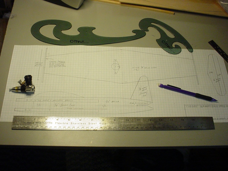

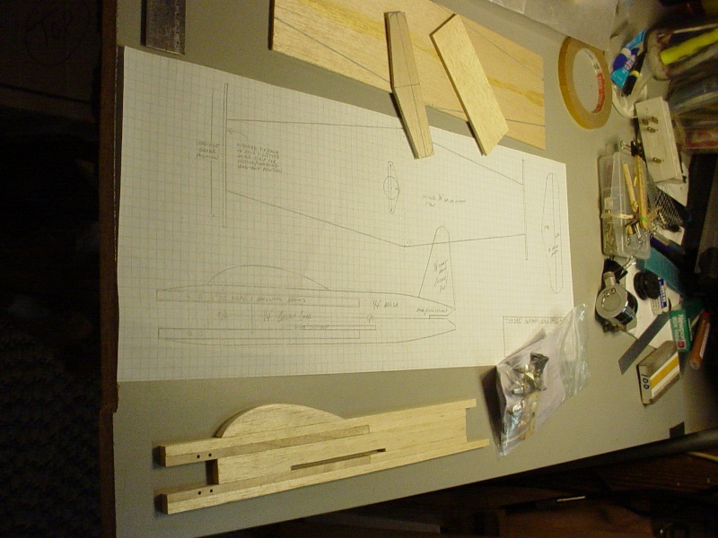
This is the start of my New Year's attempt to build a stand way-off profile scale T33 for my newly acquired Tee Dee's .049/.051 graciously gifted to me almost a year ago for my birthday by a fellow CEF member. He wanted(s) me to build a build a speed model for this upcoming contest.. and I'm afraid I'm off to a very late start. I'm off work until Tuesday though.. and today was "redesign the fuse and draw a plan" day.
I need to make engine-beams. I have a 1/4" maple piece that I have to rip-down square. I'll need to fix a thin sheet to my table-saw for it's blade to pass-through, so I can utilize a push-stick.. without worry of the stock falling through the metal plate surrounding the blade.
I used double-stick tape to secure a piece of wood to the saw's table..

Placed tight against the ripping-fence.. I proceeded to cut up through it, to a height sufficient to cut the maple stock.
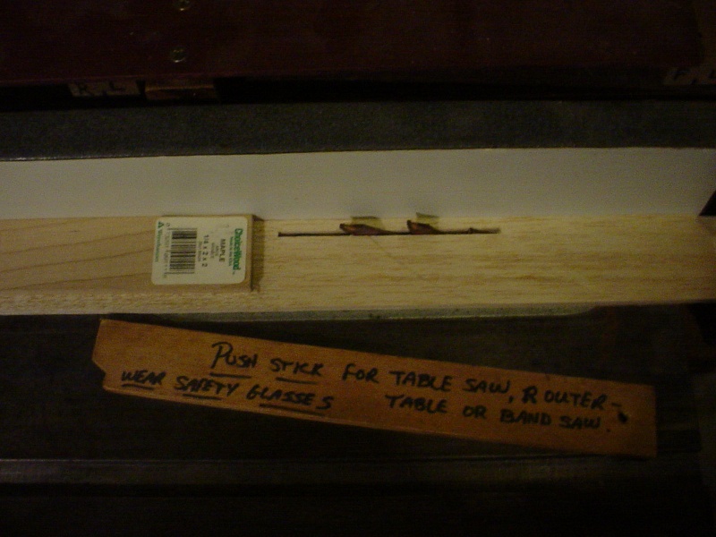
Success! Even my camera is cooperating! My caliper measures .255" square!

This design shows signs of being wicked nose-heavy.. and I'm probably out of my mind to even attempt it.. but I'm going to give it a shot. I'm going with a full-span elevator.. and no landing gear. The fuse will have guide-tabs on it's belly, for launching from a take-off dolly.
Since I had a good setting on the saw.. I figured; rip another length (15") of maple for future engine beams.. and some 1/4" sq. balsa sticks; some of which will serve as stock to "cap" the long maple beams.. top/bottom on the T33.

The fuse's tail-section is 1/4" balsa sheet, which fits between and fairs into the ends of the maple beams which are 7.5" long. Next comes drilling the Tee Dee's mount-holes and mounting the engine to establish the gap-size for the 1/4"
balsa core to key-into/between the beams and straight out to the tail. I'm hoping that this construction will provide a nice rigid nose for the Tee Dee.. as well as to spread some of the weight rearward. The wing-slot will be incorporated into the balsa-core. The 1/8" balsa sheet-wing will be glued on top of the lower beam and into the balsa core-slot.


This is the start of my New Year's attempt to build a stand way-off profile scale T33 for my newly acquired Tee Dee's .049/.051 graciously gifted to me almost a year ago for my birthday by a fellow CEF member. He wanted(s) me to build a build a speed model for this upcoming contest.. and I'm afraid I'm off to a very late start. I'm off work until Tuesday though.. and today was "redesign the fuse and draw a plan" day.
I need to make engine-beams. I have a 1/4" maple piece that I have to rip-down square. I'll need to fix a thin sheet to my table-saw for it's blade to pass-through, so I can utilize a push-stick.. without worry of the stock falling through the metal plate surrounding the blade.
I used double-stick tape to secure a piece of wood to the saw's table..

Placed tight against the ripping-fence.. I proceeded to cut up through it, to a height sufficient to cut the maple stock.

Success! Even my camera is cooperating! My caliper measures .255" square!

This design shows signs of being wicked nose-heavy..
Since I had a good setting on the saw.. I figured; rip another length (15") of maple for future engine beams.. and some 1/4" sq. balsa sticks; some of which will serve as stock to "cap" the long maple beams.. top/bottom on the T33.

The fuse's tail-section is 1/4" balsa sheet, which fits between and fairs into the ends of the maple beams which are 7.5" long. Next comes drilling the Tee Dee's mount-holes and mounting the engine to establish the gap-size for the 1/4"
balsa core to key-into/between the beams and straight out to the tail. I'm hoping that this construction will provide a nice rigid nose for the Tee Dee.. as well as to spread some of the weight rearward. The wing-slot will be incorporated into the balsa-core. The 1/8" balsa sheet-wing will be glued on top of the lower beam and into the balsa core-slot.
Last edited by roddie on Fri Jan 01, 2016 8:20 pm; edited 1 time in total
 Re: CEF speed contest Design Discussions (2014)
Roddie, I really like your Plan, your Plane and your Pattern...for the "blade guard, hole cover" My table saw has a similar over size hole for the blade, and I will use your pattern next time I have to rip down some stick stock. Thanks!

Marleysky- Top Poster


Posts : 3618
Join date : 2014-09-28
Age : 72
Location : Grand Rapids, MI
 Re: CEF speed contest Design Discussions (2014)
Marleysky wrote:Roddie, I really like your Plan, your Plane and your Pattern...for the "blade guard, hole cover" My table saw has a similar over size hole for the blade, and I will use your pattern next time I have to rip down some stick stock. Thanks!
This was a first try for me with this technique.. but it worked quite well. The push-stick is a MUST. I used a 7-1/4" dia. carbide-tipped saw-blade set approx. 1/4" higher than my stock to be cut. I measured off the ripping-fence with a machinist-rule, to the edge of the carbide-blade tip to set the cut-width. I was concerned with heat/burning.. but had no issues at all with that.
 Re: CEF speed contest Design Discussions (2014)
A bit more progress on the beams.

This old hardware package has been waiting decades for this opportunity.
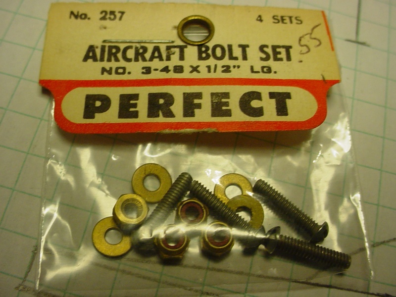
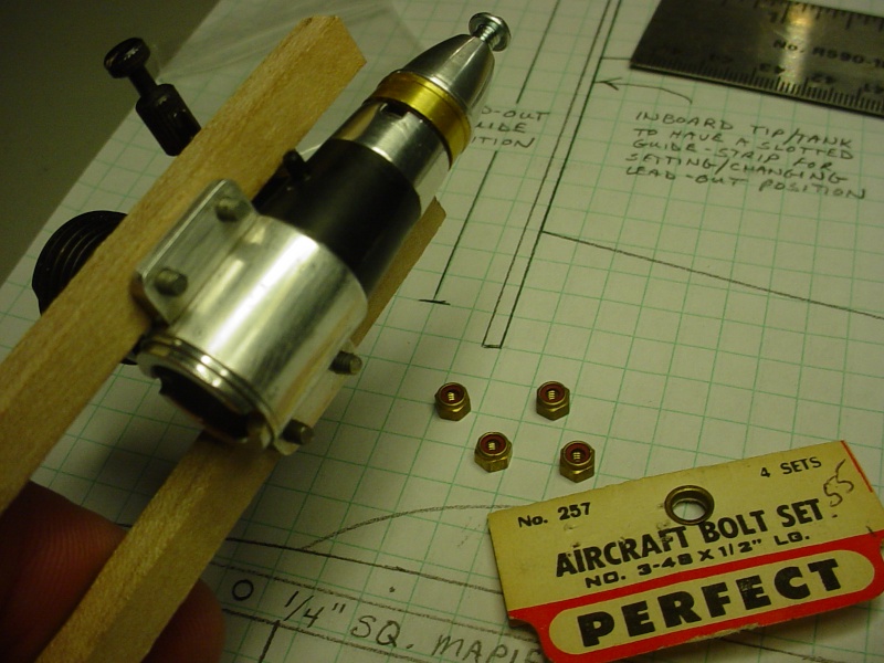


The beams extend forward for their balsa "trim-caps" to establish the curvature of the nose. I'd like to think of it as setting the engine back as far as I can in the fuse. Tee Dee's are a different animal for me. Does anybody see any potential problems with this mounting method? The cylinder is planned to be oriented outboard.

This old hardware package has been waiting decades for this opportunity.


The beams extend forward for their balsa "trim-caps" to establish the curvature of the nose. I'd like to think of it as setting the engine back as far as I can in the fuse. Tee Dee's are a different animal for me. Does anybody see any potential problems with this mounting method? The cylinder is planned to be oriented outboard.
 Re: CEF speed contest Design Discussions (2014)
did you use nylock nuts?

cox24711- Platinum Member

- Posts : 722
Join date : 2014-01-18
Age : 21
Location : Noosa Queensland Australia
 Re: CEF speed contest Design Discussions (2014)
cox24711 wrote:did you use nylock nuts?
Hi Greg! There's lock-nuts included with the hardware package.. and I figured I'd use them unless cautioned against it. I thought about using wood-screws.. but the 1/4" (6.35mm) square beams don't have a "comfortable" amount of meat to hold them.. not to mention the short length they'd need to be. There's also the risk of splitting the beam if the pilot-holes are drilled too small. I drilled .070" (1.78mm) pilot-holes first.. then enlarged them to .098" (2.5mm) which is the hole size in the engine-lug. A 3-48 machine-screw has a .095" diameter. The spacing between holes is .375" (9.53mm) on center for the Cox Tee Dee .049 engine. I used an awl to mark the holes beforehand.. to help start the drill in the center of the beam.

 Re: CEF speed contest Design Discussions (2014)
I assume your going with a tank? If what I'm seeing is correct then yes I see a problem. The TD is very sensitive to the tank. If the tank is going to be mounted on the outboard side of your engine crutch, the centerline of engine is now further inboard. In the event you do mount a tank place it on the same side of the beams as your engine lugs. In other words if that cylinder is to be mounted for outboard position, the tank will be on the inboard side which means the tank has to be replumbed if your decide to use a stock tank. This now leads to other problems because the faster the plane flies the richer the fuel mix goes. Where most tanks typically get shimmed up and down, this now would require to be shimmed left to right which isn't practical unless you leave that area open for access or shim your engine off the beams. Just for the record, Cox engines were meant to be mounted with 3-48 screws which are increasingly getting rarer. Ken
Just for clarification, is the TD allowed to be used in these speed contests? I wasn't aware of that if it was as I have current designs using the TD.
Just for clarification, is the TD allowed to be used in these speed contests? I wasn't aware of that if it was as I have current designs using the TD.

Ken Cook- Top Poster

- Posts : 5642
Join date : 2012-03-27
Location : pennsylvania
 Re: CEF speed contest Design Discussions (2014)
I would be tempted to use the outboard wing tank of the T-33 for a long thin bladder as the fuel and tip weight for the brief flights

fredvon4- Top Poster


Posts : 4012
Join date : 2011-08-26
Age : 69
Location : Lampasas Texas
 Re: CEF speed contest Design Discussions (2014)
Roddie I have never seen anyone mount the engine as you have it why did you chose this way ?  as Ken said about the centering of the engine with the crankcase on the inboard side . getback
 as Ken said about the centering of the engine with the crankcase on the inboard side . getback

getback- Top Poster


Posts : 10442
Join date : 2013-01-18
Age : 67
Location : julian , NC
 Re: CEF speed contest Design Discussions (2014)
Ken Cook wrote:I assume your going with a tank? If what I'm seeing is correct then yes I see a problem. The TD is very sensitive to the tank. If the tank is going to be mounted on the outboard side of your engine crutch, the centerline of engine is now further inboard. In the event you do mount a tank place it on the same side of the beams as your engine lugs. In other words if that cylinder is to be mounted for outboard position, the tank will be on the inboard side which means the tank has to be replumbed if your decide to use a stock tank. This now leads to other problems because the faster the plane flies the richer the fuel mix goes. Where most tanks typically get shimmed up and down, this now would require to be shimmed left to right which isn't practical unless you leave that area open for access or shim your engine off the beams. Just for the record, Cox engines were meant to be mounted with 3-48 screws which are increasingly getting rarer. Ken
Just for clarification, is the TD allowed to be used in these speed contests? I wasn't aware of that if it was as I have current designs using the TD.
Hi Ken, Yes.. there is a Tee Dee .049/.051 class now.. and the line-length has been reduced from 42 to 35 feet. I was planning to run a balloon tank in a streamlined capsule . Would it's position still be critical? The engine position was somewhat dictated by my desire to extend the beams forward to just behind the prop-driver. The pressure nipple sticks down below the lug slightly. I could notch the beam to clear the nipple I suppose. Thanks as always for the advice.
 Re: CEF speed contest Design Discussions (2014)
roddie wrote:cox24711 wrote:did you use nylock nuts?
Hi Greg! There's lock-nuts included with the hardware package.. and I figured I'd use them unless cautioned against it. I thought about using wood-screws.. but the 1/4" (6.35mm) square beams don't have a "comfortable" amount of meat to hold them.. not to mention the short length they'd need to be. There's also the risk of splitting the beam if the pilot-holes are drilled too small. I drilled .070" (1.78mm) pilot-holes first.. then enlarged them to .098" (2.5mm) which is the hole size in the engine-lug. A 3-48 machine-screw has a .095" diameter. The spacing between holes is .375" (9.53mm) on center for the Cox Tee Dee .049 engine. I used an awl to mark the holes beforehand.. to help start the drill in the center of the beam.
COOLIES p.s thanks for the conversions!

cox24711- Platinum Member

- Posts : 722
Join date : 2014-01-18
Age : 21
Location : Noosa Queensland Australia
 Re: CEF speed contest Design Discussions (2014)
getback wrote:Ok here you go some cuts / more sanding and sanding primer cut with clear dope


Yes I am going to fly a Knife Edge the whole flight LOL Thanks Kim for the Kicking I needed. Bearers tomorrow sanding and epoxy. Need to figure out the tail feathers placement / getback
let me guess mustang p51 or p40 there is a radiator under the wing so that mean it could not have a prat and whitney wasp (they are air cooled) meaning there was no choice unless it is not american!

cox24711- Platinum Member

- Posts : 722
Join date : 2014-01-18
Age : 21
Location : Noosa Queensland Australia
 Re: CEF speed contest Design Discussions (2014)
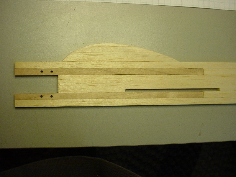
I've come to my senses.. and filed that notch in the beam to clear the pressure-nipple on the Tee Dee.

The wing-position is a LoOoOong ways back on this jet..

I cut a piece of 1/4" balsa to fit between the beams and all the way out to the tail. It has the 4" root-chord wing cut-out slot. Now I will piece-in 1/4" balsa; top and bottom to create the fuse's profile.


The wing-position is a LoOoOong ways back on this jet..

I cut a piece of 1/4" balsa to fit between the beams and all the way out to the tail. It has the 4" root-chord wing cut-out slot. Now I will piece-in 1/4" balsa; top and bottom to create the fuse's profile.

 Re: CEF speed contest Design Discussions (2014)
Nothing wrong with the under the beams mount of the motor. It looks odd, but it has been done by others before. The engine won't care.
Wood screws are a bad idea on beam mount engines. Use bolts (machine screws) and lock nuts, or double nut, or use CA or lock-tite in the threads. The side loading will cause wood screws to pull out over time. With firewall mounting the loading does not open the hole up in the same way.
Phil
Wood screws are a bad idea on beam mount engines. Use bolts (machine screws) and lock nuts, or double nut, or use CA or lock-tite in the threads. The side loading will cause wood screws to pull out over time. With firewall mounting the loading does not open the hole up in the same way.
Phil

pkrankow- Top Poster

- Posts : 3025
Join date : 2012-10-02
Location : Ohio
 Re: CEF speed contest Design Discussions (2014)
Looking good Roddie here is were I am , thought about what U said man I am too far along to redo it now (pm) Greg its suppose to bee a P-51 D 
 when it breaks I will fix it
  getback

 when it breaks I will fix it
  getback

getback- Top Poster


Posts : 10442
Join date : 2013-01-18
Age : 67
Location : julian , NC
 Re: CEF speed contest Design Discussions (2014)
That's right Eric! I like the paint colors! Is that Aero-Gloss "Silvaire Aluminum"? Dayeeem.. looks like you sprayed it. Nice sanding job on the fuse contour!
I'm making more progress than I thought I would today.

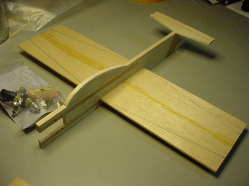
I'm making more progress than I thought I would today.


 Re: CEF speed contest Design Discussions (2014)
looking good Roddie

akjgardner- Diamond Member


Posts : 1602
Join date : 2014-12-28
Age : 65
Location : Greensberg Indiana
 Re: CEF speed contest Design Discussions (2014)
looking good Ericgetback wrote:Looking good Roddie here is were I am , thought about what U said man I am too far along to redo it now (pm) Greg its suppose to bee a P-51 D
when it breaks I will fix it
getback

akjgardner- Diamond Member


Posts : 1602
Join date : 2014-12-28
Age : 65
Location : Greensberg Indiana
 Re: CEF speed contest Design Discussions (2014)
akjgardner wrote:looking good Roddie
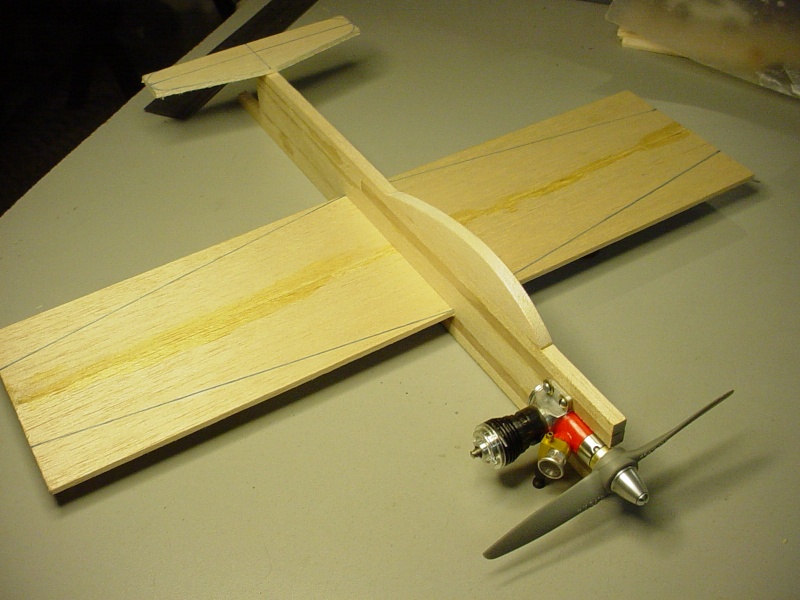
Thanks Joe! This is the engine that was given to me to compete with.. I'm a little nervous though. I wouldn't want to have a mishap with this one.

 Re: CEF speed contest Design Discussions (2014)
Thanks guys ,not much more to do just need to get to it !! going to try and work on it today , I need to test another engine against the one I ran the other day and decide on a tank! The paint for fuse was Krylon (satin nickel/brushed metallic ) and Rust -Opium for the blue.  Roddie your moving right along , what engine is that .051 ? Those beams running back that far should give you plenty of strength and I like the way they look too . I want to get out today and do some flying it will bee 56 * high and then the weather will fall off the grid for some cold days /nites and then roller coaster back to 61 * next weekend , that's when I want to use that window to fly this baby and it really needs to go the first time or with maybe a quick fix if necessary
  getback


getback- Top Poster


Posts : 10442
Join date : 2013-01-18
Age : 67
Location : julian , NC
 Re: CEF speed contest Design Discussions (2014)
getback wrote: The paint for fuse was Krylon (satin nickel/brushed metallic ) and Rust -Opium for the blue.Roddie your moving right along , what engine is that .051 ? Those beams running back that far should give you plenty of strength and I like the way they look too .
Rust-Opium.. I've never tried that..
 looks really nice man! Are you gonna clear-it.. or does it test as fuel resistant? I saved photos from a Krylon orange-color test that you did a while back.
I bought a can of Minwax aerosol clear-gloss lacquer a few months ago (on clearance)


I need to test for both; undercoat compatibility.. and fuel resistance.
Yes, that's a Tee Dee .051 in the recent T33 model photos. I mounted it to keep the psych going! I can't afford to have this build take the amount of time that the Rare-Bear did..
 Re: CEF speed contest Design Discussions (2014)
That stuff was spray and very thin (runny) had to wipe it the first time then two coats , if I put some decals on it witch I have trouble figuring out the right ones I will clear coat it . I have 3 difft. clears to pick from all should be good either way though . the paint 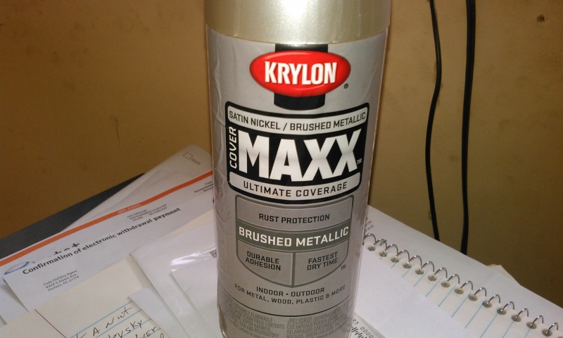 the clear
 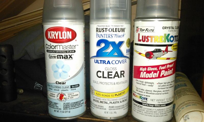 I got to gooooo right now this is fun but ,,, not getting it done Later ! getback
 the clear
  I got to gooooo right now this is fun but ,,, not getting it done Later ! getback
getback- Top Poster


Posts : 10442
Join date : 2013-01-18
Age : 67
Location : julian , NC
 Re: CEF speed contest Design Discussions (2014)
roddie wrote:getback wrote: The paint for fuse was Krylon (satin nickel/brushed metallic ) and Rust -Opium for the blue.Roddie your moving right along , what engine is that .051 ? Those beams running back that far should give you plenty of strength and I like the way they look too .
Rust-Opium.. I've never tried that..The Satin-Nickel is sweet! So you paint-brushed it
looks really nice man! Are you gonna clear-it.. or does it test as fuel resistant? I saved photos from a Krylon orange-color test that you did a while back.
I bought a can of Minwax aerosol clear-gloss lacquer a few months ago (on clearance)
I need to test for both; undercoat compatibility.. and fuel resistance.
Yes, that's a Tee Dee .051 in the recent T33 model photos. I mounted it to keep the psych going! I can't afford to have this build take the amount of time that the Rare-Bear did..
This is lacquer, not polyurethane. It is not fuel proof. This is pretty similar to fingernail polish. It _should_ be compatible with dope. It would work in the same manner as using nitrate under butylrate, even though the nitrate is not fuel proof. Test anyways.
After a suitable cure time, several days at least, it should be compatible with enamel. HOWEVER be careful as dope/enamel/dope is not a good layer combination. The enamel will allow the lower layer of dope (or lacquer) to soften causing the enamel to slough (fall off).
Phil

pkrankow- Top Poster

- Posts : 3025
Join date : 2012-10-02
Location : Ohio
 Re: CEF speed contest Design Discussions (2014)
Thanks Phil.. finishing is not my forte. I can use all the help I can get! 
I set my model into the take-off dolly.. to see what I need to do.
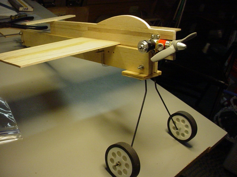

I have a couple options.. slot the belly of the fuse, when I figure out the balance-point.. or install a vertical pin that sticks down from the same place. A pin will help protect the needle somewhat when landing.. but I see now that I really need to take more action for that condition.
A variation of this might work.. (as if I don't have enough weight forward.. )
)
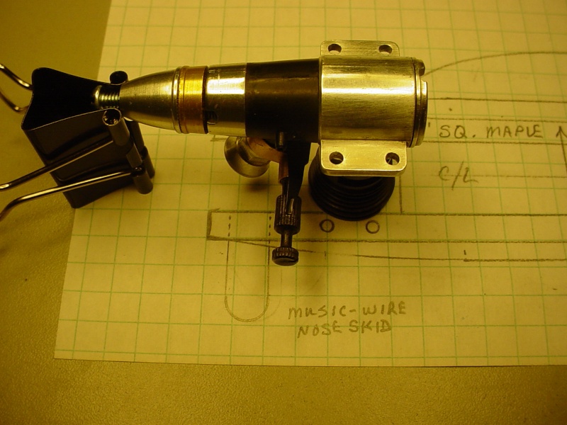
I set my model into the take-off dolly.. to see what I need to do.


I have a couple options.. slot the belly of the fuse, when I figure out the balance-point.. or install a vertical pin that sticks down from the same place. A pin will help protect the needle somewhat when landing.. but I see now that I really need to take more action for that condition.
A variation of this might work.. (as if I don't have enough weight forward..

Page 18 of 20 •  1 ... 10 ... 17, 18, 19, 20
 Similar topics
» CEF speed contest Design Discussions
» CEF T-Shirt Design Contest
» *VOTE* CEF T-Shirt Design Contest
» Reed Speed qualifying photos... Post em if ya got em. (2014)
» What is it???
» CEF T-Shirt Design Contest
» *VOTE* CEF T-Shirt Design Contest
» Reed Speed qualifying photos... Post em if ya got em. (2014)
» What is it???
Page 18 of 20
Permissions in this forum:
You cannot reply to topics in this forum

 Rules
Rules

