Log in
Search
Latest topics
» Cox 020 PeeWee rebuild questions by LooseSpinner99 Today at 6:13 pm
» Did you spot the Cox engine in this NASA research video?
by balogh Today at 5:08 pm
» Roger Harris revisited
by rsv1cox Today at 3:44 pm
» Retail price mark-up.. how much is enough?
by Ken Cook Today at 2:54 pm
» Happy 77th birthday Andrew!
by Admin Today at 12:34 pm
» Tee Dee .020 combat model
by 1/2A Nut Today at 10:34 am
» Purchased the last of any bult engines from Ken Enya
by sosam117 Today at 8:15 am
» TEE DEE Having issues
by balogh Today at 7:42 am
» Cox films/videos...
by Coxfledgling Today at 4:46 am
» My N-1R build log
by roddie Today at 12:32 am
» Landing-gear tips
by roddie Yesterday at 6:17 pm
» My latest doodle...
by roddie Yesterday at 10:43 am
Cox Engine of The Month
Roddie's combat model for reed power.
Page 1 of 1
 Roddie's combat model for reed power.
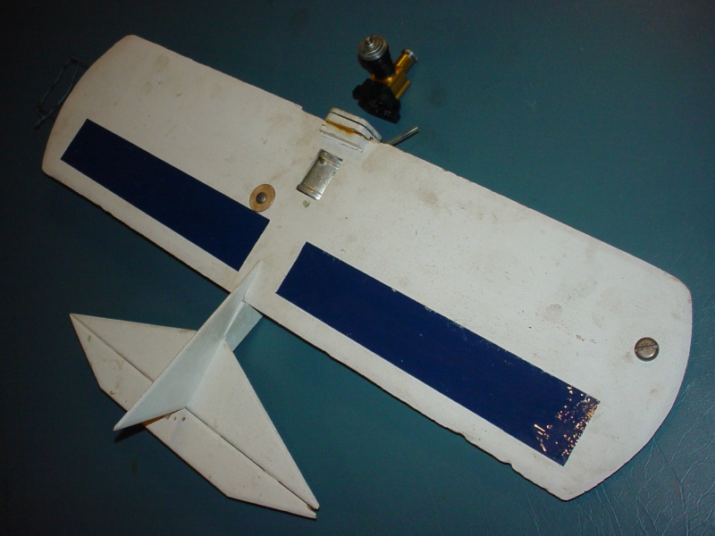
I designed this model in the early 90's. I've never flown it... because I could never launch it. I often thought about making a R.O.G. dolly.. for use with my "pin-stooge", but it never happened. A "bathmat" stooge-launch.. off a card-table might work.. but with the flat wing, I think it would be a lot more tricky. (I had never known about the bathmat stooge until I joined this forum recently)
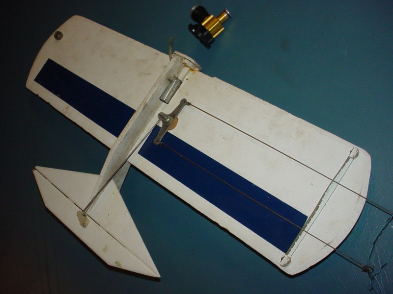
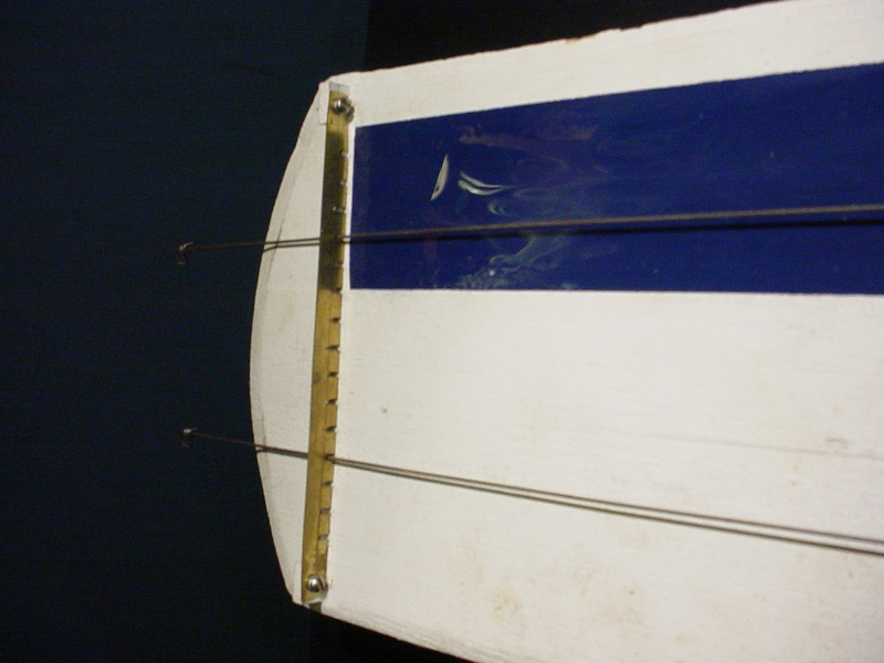
This model's wing is about 97 squares; 1/8" flat sheet balsa, as are the tail-feathers. I chose to lighten the wing with rectangular cut-outs 2/3 rearward the leading edge, and seal with Mono-kote strips. I also made an adj. lead-out guide to try.
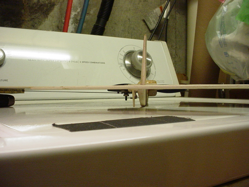
The profile fuse is 1/4" balsa, 1" x 8" long.. with a plywood firewall sized for a horseshoe back-plate, just 1/4" forward the leading edge, "keyed" into the fuse and braced at the wing junctions. The fuse is below the wing and stabilizer.
Hinges are sm. Dubro pinned type.. (I had a lot more patience back then)
The fuel tank is about 8cc capacity and centrally mounted on the c.g. If I build another one someday, I think I'll try a balloon tank and maybe a Mono-kote hinge. (these are also things I haven't tried before)
Roddie


 Re: Roddie's combat model for reed power.
Roddie, that looks like a good design. My Stuntman 23 launched just fine from the bathmat, but I bungeed my PVC lawn table atop a bar stool to give it room to dip. However it's mostly brute force that keeps it up for the first few feet, and I never tried it with a Bee engine.roddie wrote:A "bathmat" stooge-launch.. off a card-table might work.. but with the flat wing, I think it would be a lot more tricky. (I had never known about the bathmat stooge until I joined this forum recently)
For a lower power engine, I recommend launching from the downwind side of the circle plus a few degrees so that it starts into some headwind pretty soon. The downwind element will keep some tension, the elevator will tilt it up and the wings will act like a kite as it moves into the headwind. Prepare to dance for a half circle.
With high power and a built up wing, NEVER launch into a headwind or you'll instantly be in a slack line wingover... or worse, an instant 4 foot inside loop. You want to be 45deg behind your low power launch spot. Part crosswind, part tailwind. With any but the most power, a full on tail wind will drop it scary close to the ground as soon as you pull out. Figuring out how much UP is different for every plane.
All that being said, it's not as tricky as I make it sound, but I just wanted to explain the strategy.
Rusty
_________________
Don't Panic!
...and never Ever think about how good you are at something...
while you're doing it!
My Hot Rock & Blues Playlist
...and never Ever think about how good you are at something...
while you're doing it!
My Hot Rock & Blues Playlist

RknRusty- Rest In Peace

- Posts : 10869
Join date : 2011-08-10
Age : 68
Location : South Carolina, USA
 Re: Roddie's combat model for reed power.
Looks like a nice construction. Rusty's bathroom mat stooge will launch that thing just fine.
I expect a flight report soon!
I expect a flight report soon!

Cribbs74- Moderator


Posts : 11907
Join date : 2011-10-24
Age : 50
Location : Tuttle, OK
 Re: Roddie's combat model for reed power.
RknRusty wrote:Roddie, that looks like a good design. My Stuntman 23 launched just fine from the bathmat, but I bungeed my PVC lawn table atop a bar stool to give it room to dip. However it's mostly brute force that keeps it up for the first few feet, and I never tried it with a Bee engine.roddie wrote:A "bathmat" stooge-launch.. off a card-table might work.. but with the flat wing, I think it would be a lot more tricky. (I had never known about the bathmat stooge until I joined this forum recently)
For a lower power engine, I recommend launching from the downwind side of the circle plus a few degrees so that it starts into some headwind pretty soon. The downwind element will keep some tension, the elevator will tilt it up and the wings will act like a kite as it moves into the headwind. Prepare to dance for a half circle.
With high power and a built up wing, NEVER launch into a headwind or you'll instantly be in a slack line wingover... or worse, an instant 4 foot inside loop. You want to be 45deg behind your low power launch spot. Part crosswind, part tailwind. With any but the most power, a full on tail wind will drop it scary close to the ground as soon as you pull out. Figuring out how much UP is different for every plane.
All that being said, it's not as tricky as I make it sound, but I just wanted to explain the strategy.
Rusty
Yes.. I figured that some dancing will be done regardless..
 ..... maybe a dolly might be a safer approach. I had an idea for a "T"-shaped fixture (2 wheels at the front) with a center saddle/groove for a profile fuse to fit in/rise-up out of, with a high angle of attack and rear forks to hold the tail down when released from a "pin" stooge... which would still engage the model.. for safety. Square Spruce stock... 1/4" would be lightweight.. with a plywood gusset at the forward "T" joint and 2-3" dia. foam wheels for taking off in grass. The wings' leading edge would ride up against 2 padded posts close to the center line which the fuse would straddle. The rear of the dolly could be weighted if needed.. if there were nose-over problems.
 May seem a little complicated... (I'll make a sketch for clarity) but if it works and if you're flying alone.. it would eliminate the need for a table at the field, when flying models without landing gear... and may even provide a smoother launch.
Roddie
 Re: Roddie's combat model for reed power.
Cribbs74 wrote:Looks like a nice construction. Rusty's bathroom mat stooge will launch that thing just fine.
I expect a flight report soon!
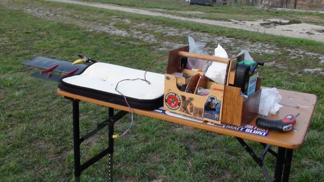
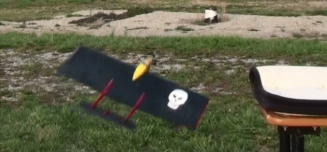
If you can get a taller platform, your plane will have a little more altitude to get going. I use my shooting table with it's legs extended to bring everything up to above waist-high, AND really like having the rest of my gear there too, rather than laying it out on the ground.
Probably make something real similar with some flooring ply...

Kim- Top Poster


Posts : 8625
Join date : 2011-09-06
Location : South East Missouri
 Re: Roddie's combat model for reed power.
An "embarrassingly" old thread here.. that I hope to revive. Cross reference thread; https://www.coxengineforum.com/t7301-reed-valve-stunt#127353
I drew some outlines of the parts back in 1993 when I built the model.
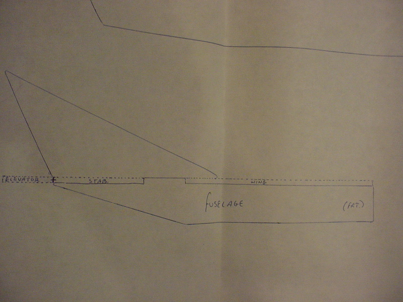
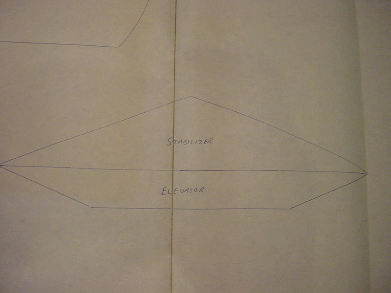
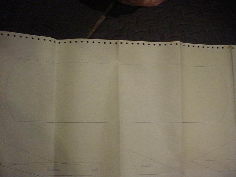
I didn't finish the plan.. because I never flew the model.. but have several full-plans of my other designs that "have" flown.
I will upgrade these to include all measurements and pertinent construction info. because I have faith that it might be a good little flyer.
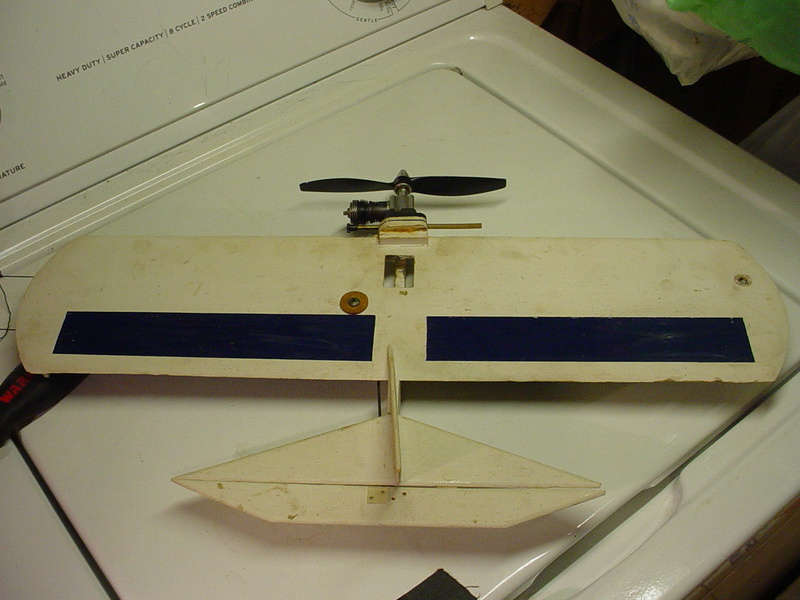
Materials are pretty much standard 1/2A sheet-wing fair. Obtain 1/8" sheet-balsa for the wing and tail-feathers.. (two pieces of 3" x 36" sheet) The wing is 20" span x 5" constant-chord (100 sq. in.) a small piece of 1/4" balsa (1" x 8") for the fuse.. and small scraps of 1/4", 3/16" balsa and 1/8" 5-ply aircraft Birch for the firewall. The wing is cored (not shown yet..) with 1" x 7" voids/cut-outs 3/4" forward the T/E and 1" out from the fuse, both panels. I covered the voids top/bottom with mono-kote in an effort to save weight. The nose-moment as-designed is short.. and the engine-configuration is for a Cox .049 fitted with a horseshoe back-plate mounted horizontally. As can be seen in the photos/drawings; the wing sits "atop" the fuse. I made a "pocket" in the wing and fuse to place a wedge-tank at the theoretical C of G.
My 1/8" balsa sheet estimate is "liberal".. and I'll have to calculate for the best yield. The tail-span is 10" and utilizes a 2" chord on the stab.. and 1" chord on the elev. A more accurate preliminary estimate would be "one sheet" of 3" x 36" and one sheet of 2" x 36". This should be enough to build "two" models. The 1/4" fuse; I'd be willing to bet you already have in scrap laying around the shop.. as well as the material for the firewall.
I'll be test-flying this model with some mods. As shown; it has an outboard tip-weight of .25oz. It also has .031" solid lead-outs and a "Perfect" metal bell-crank. That tip-weight was to offset the inboard wing's hardware. The mods will consist of swapping to .015" solid-wire lead-outs, a Sig #SH-234 nylon 1/2A bell-crank.. and running a 2-blade Cox black 6" x 2" "L/H" prop. This should put the finish-weight close to 5oz. The white finish you see; was an experimental use of "Bin-Seal" (oil-based white-pigmented shellac) I don't know that I'd recommend that...
  but it seemed like a good idea when I did it back in 1993. Being a "flat-white" finish.. the model has gotten a bit dirty.. even though it has never flown. It has however survived several hanger-storage spots and moves over the last 23 years. I'll probably fill a few dings, give it a quick-sanding, touch-up with some flat-white and spray a few light coats of crystal-clear Top Flight Lustre-Kote. On short 17-18' lines, I'm hoping that it will be controllable when "bathmat-stooge" launched from a height of 30-32" (x3 stacked milk-bottle crates).. There's always the option later.. to upgrade to a more aggressive engine/prop combo and longer lines. Maybe 30-35' lines with a "Killer-Bee" configured-engine.
I'll work on the plan.. and post photos of the added details.
I drew some outlines of the parts back in 1993 when I built the model.


I didn't finish the plan.. because I never flew the model..
I will upgrade these to include all measurements and pertinent construction info. because I have faith that it might be a good little flyer.
Materials are pretty much standard 1/2A sheet-wing fair. Obtain 1/8" sheet-balsa for the wing and tail-feathers.. (two pieces of 3" x 36" sheet) The wing is 20" span x 5" constant-chord (100 sq. in.) a small piece of 1/4" balsa (1" x 8") for the fuse.. and small scraps of 1/4", 3/16" balsa and 1/8" 5-ply aircraft Birch for the firewall. The wing is cored (not shown yet..) with 1" x 7" voids/cut-outs 3/4" forward the T/E and 1" out from the fuse, both panels. I covered the voids top/bottom with mono-kote in an effort to save weight. The nose-moment as-designed is short.. and the engine-configuration is for a Cox .049 fitted with a horseshoe back-plate mounted horizontally. As can be seen in the photos/drawings; the wing sits "atop" the fuse. I made a "pocket" in the wing and fuse to place a wedge-tank at the theoretical C of G.
My 1/8" balsa sheet estimate is "liberal".. and I'll have to calculate for the best yield. The tail-span is 10" and utilizes a 2" chord on the stab.. and 1" chord on the elev. A more accurate preliminary estimate would be "one sheet" of 3" x 36" and one sheet of 2" x 36". This should be enough to build "two" models. The 1/4" fuse; I'd be willing to bet you already have in scrap laying around the shop.. as well as the material for the firewall.
I'll be test-flying this model with some mods. As shown; it has an outboard tip-weight of .25oz. It also has .031" solid lead-outs and a "Perfect" metal bell-crank. That tip-weight was to offset the inboard wing's hardware. The mods will consist of swapping to .015" solid-wire lead-outs, a Sig #SH-234 nylon 1/2A bell-crank.. and running a 2-blade Cox black 6" x 2" "L/H" prop. This should put the finish-weight close to 5oz. The white finish you see; was an experimental use of "Bin-Seal" (oil-based white-pigmented shellac)
I'll work on the plan.. and post photos of the added details.
 Re: Roddie's combat model for reed power.
Why not just fly it as is? Good chance it's going to wreck. Don't get attached.
Once it gets airborne you will be charged up, probably enough to build another or finish the ones you have.
Ron
Once it gets airborne you will be charged up, probably enough to build another or finish the ones you have.
Ron

Cribbs74- Moderator


Posts : 11907
Join date : 2011-10-24
Age : 50
Location : Tuttle, OK
 Re: Roddie's combat model for reed power.
Cribbs74 wrote:Why not just fly it as is? Good chance it's going to wreck. Don't get attached.
Once it gets airborne you will be charged up, probably enough to build another or finish the ones you have.
Ron
I def. see your point Ron.. but it does need a "little" touching-up/filling of some bare-wood spots/dings from a few bumps/falls it's suffered. As I mentioned; I'd like to spray a couple light coats of clear gloss over the existing flat-white, to help keep it from getting more dirty. Doing that will involve some light sanding. Easier/better accomplished by removing the bell-crank and lead-outs.. which I wanted to swap-out for lighter-weight parts. This should make it about a 1/2oz. lighter.. (at least..) which is a lot for an airplane this small.
If I wreck it.. I wreck it.
I got an engine picked-out. #3/slit-cylinder/non-SPI with great compression. It's been years since there's been an engine mounted. It seems pretty well balanced.

 Re: Roddie's combat model for reed power.
Cribbs74 wrote:Why not just fly it as is? Good chance it's going to wreck. Don't get attached.
Once it gets airborne you will be charged up, probably enough to build another or finish the ones you have.
Ron


 Good RiBBing , Ron (you know that's right !! )
getback- Top Poster


Posts : 10443
Join date : 2013-01-18
Age : 67
Location : julian , NC
 Re: Roddie's combat model for reed power.
I certainly wasn't trying to be snarky, just realistic. To me it would make more sense just to sling it and if it survives then spend a little time on it and make it nice.

Cribbs74- Moderator


Posts : 11907
Join date : 2011-10-24
Age : 50
Location : Tuttle, OK
 Re: Roddie's combat model for reed power.
Cribbs74 wrote:I certainly wasn't trying to be snarky, just realistic. To me it would make more sense just to sling it and if it survives then spend a little time on it and make it nice.
Ron.. You've been a good supporter and catalyst for my model activities since my joining CEF. No worries man! I just need to find my way. Like everyone else.. life happens. I get charged-up on an idea.. and then get thrown a curve-ball in the way of available-time.. mood.. etc. I'm too active here with my ideas/suggestions. That energy would be better-spent offline in the shop and in the field.. and reporting successes/failures. It's hard for me; not to login daily here, and comment on topics that pique my interest. It's very often the "high-point" of my day.
Back to the bathmat-stooge launch of my proposed-model..
I've misplaced the wedge-tank that it was designed around..
 renamed "RodBat"...
I've been working like a fiend this last week.. getting airplanes ready to fly. This one received a little attention this afternoon. It looked pretty bad. I had painted it with flat-white primer decades ago. Not wanting to spend too much time on it; I lightly sanded it with 240 paper and gave it a few coats of gloss-white Rust-Oleum.
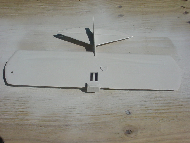
The wedge-tank that fit in the wing's cut-out has problems.. so I'm going to try running a long-shaped balloon-tank in a protective tube, under the outboard wing along-side the fuse.

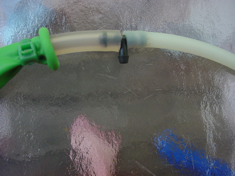
Here's a shot of the fuel pick-up. I notched a few inlets using a hole-punch for assured-flow as the balloon collapses.
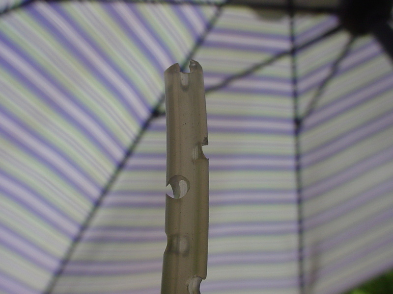
The small zip-tie seems to seal well around the neck of the balloon and silicone fuel-line. The "tee" is for air-evacuation with either a closed needle or pinching-off the engine's feed-line.. and will be capped after fueling.
Once the paint dries sufficiently, I'll re-install the hardware/controls.. and mount one of the Cox .049 reed-valve engines that I rebuilt this past week. I'm sticking with the L/H prop plan.. and "Rusty-Style" bathmat launching-stooge.

The wedge-tank that fit in the wing's cut-out has problems.. so I'm going to try running a long-shaped balloon-tank in a protective tube, under the outboard wing along-side the fuse.


Here's a shot of the fuel pick-up. I notched a few inlets using a hole-punch for assured-flow as the balloon collapses.

The small zip-tie seems to seal well around the neck of the balloon and silicone fuel-line. The "tee" is for air-evacuation with either a closed needle or pinching-off the engine's feed-line.. and will be capped after fueling.
Once the paint dries sufficiently, I'll re-install the hardware/controls.. and mount one of the Cox .049 reed-valve engines that I rebuilt this past week. I'm sticking with the L/H prop plan.. and "Rusty-Style" bathmat launching-stooge.
 Re: Roddie's combat model for reed power.
I'm still working on this one. Not a whole lot to report.. but I want to install a tube under the outboard-wing to support/protect a balloon-type fuel tank. There was a cut-out in the wing/fuse for a hard-tank which I plugged with balsa. It still needs to be filled/sealed/painted. This will make the area solid for mounting the tube.
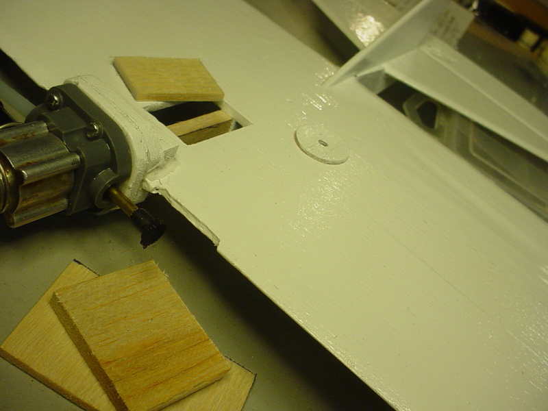
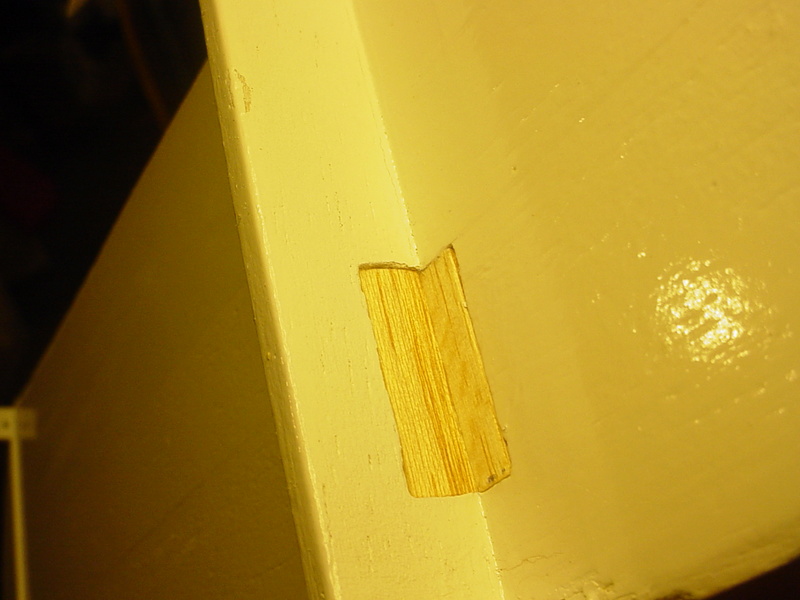
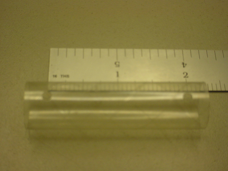
The tube is a very lightweight thin-wall/clear-plastic one which I punched two holes in for mounting through the fuse with twisty-tie.
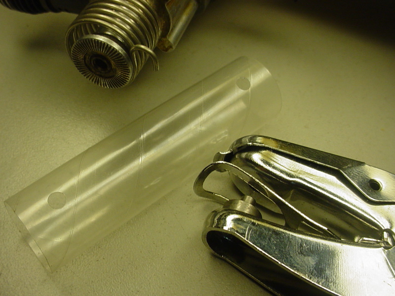
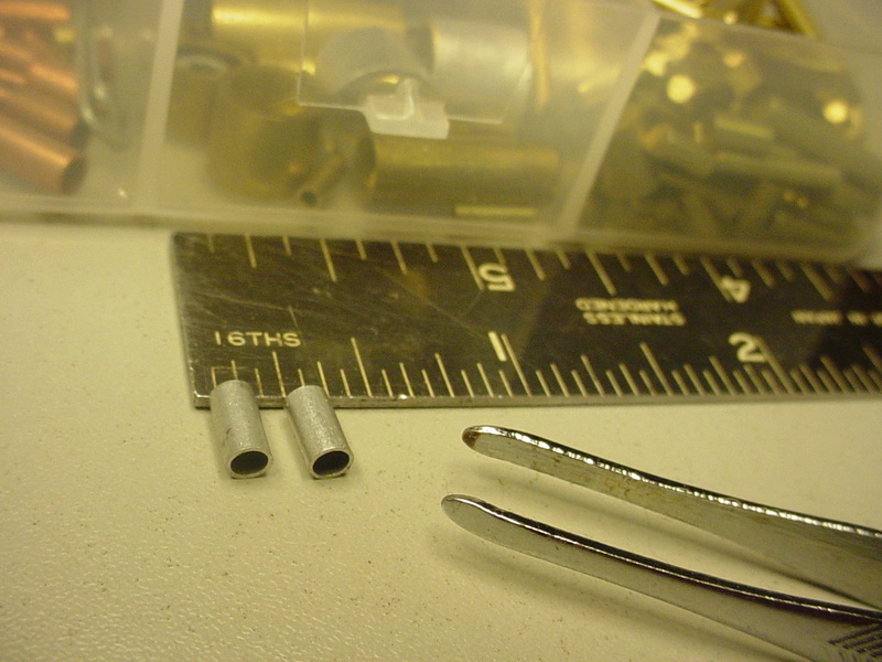
These two small aluminum tubes will sleeve the mount-holes in the fuse.


The tube is a very lightweight thin-wall/clear-plastic one which I punched two holes in for mounting through the fuse with twisty-tie.


These two small aluminum tubes will sleeve the mount-holes in the fuse.

 Re: Roddie's combat model for reed power.
Looking GOOD !! That's one wild looking set of tail feathers she has  Never had an all white plane before , Glad to hear you got the engines straightened out to run on the planes .
  Looking forward to the big day i am sure !!
 Looking forward to the big day i am sure !!

getback- Top Poster


Posts : 10443
Join date : 2013-01-18
Age : 67
Location : julian , NC
 Re: Roddie's combat model for reed power.
getback wrote:Looking GOOD !! That's one wild looking set of tail feathers she hasNever had an all white plane before , Glad to hear you got the engines straightened out to run on the planes .
Looking forward to the big day i am sure !!
Thanks Eric. I think I may be in trouble with the CG-balance since spraying that gloss-white..
 The metal bell-crank assembly and .031" solid-wire lead-outs are really oversize for this model. The pushrod is .062" wire, which is really overkill/heavy.. as short as it is.
 Check this out.. This control set-up is better suited to a .15 engine sized model..
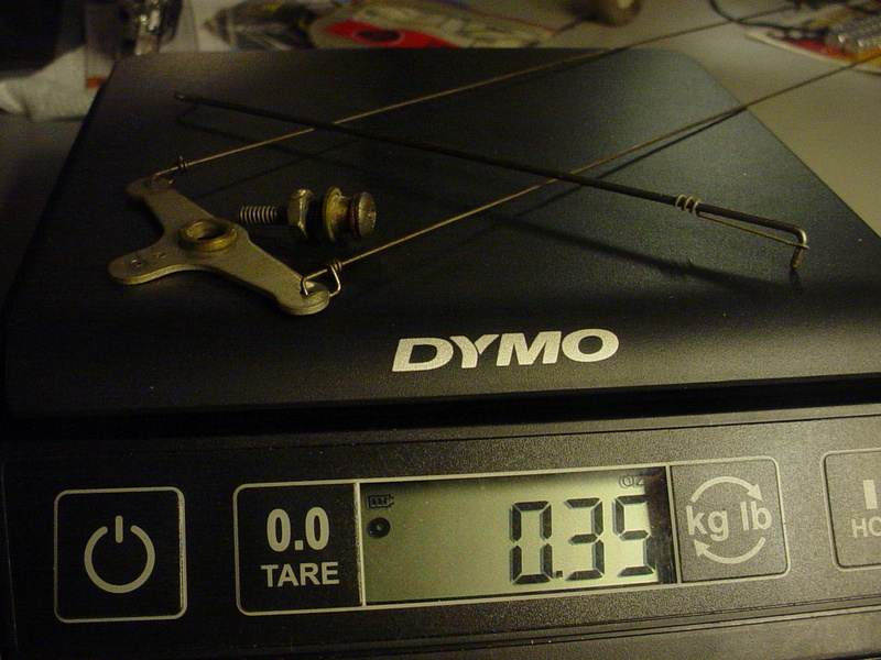
That's just ridiculous.. but it was all I had to work with when I built it. I have much lighter-weight materials that I can substitute now. It's a little more work than I planned on.. but I don't mind. I'd rather spend the extra time trying to get it in the "ball-park" balance-wise.. than be hasty.. have it crash on the maiden and wonder if I should have done the work. This airplane's nose is its engine.. so if I need nose-weight to get it to balance, I also have a spinner hub-nut from a Cox Super-Stunter that will add considerable weight.. if it comes down to that.
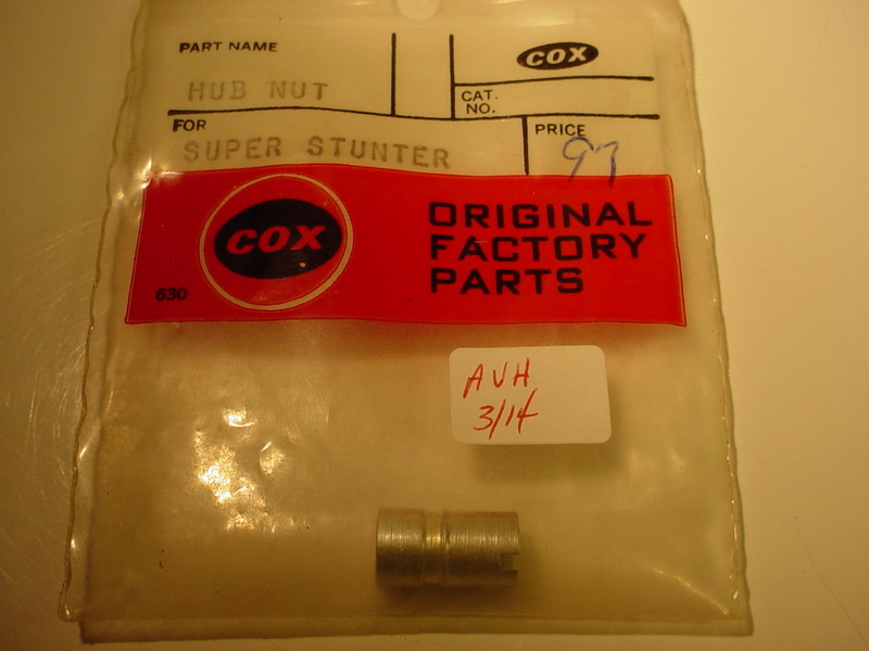
It's a heavy piece when compared to this standard Cox spinner hub-nut..
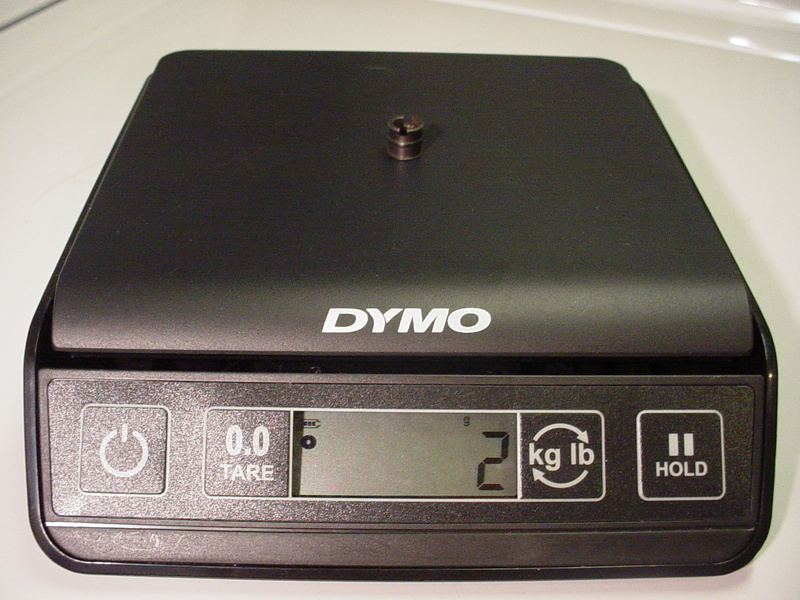

I bought two of those SS hub nuts a couple years ago from a LHS that was going out of business. Besides being OEM Cox parts.. I knew that they could be used for this purpose some day if needed. Perhaps the Super-Stunter ended-up needing this part after the model was initially designed?
 The stk./cat.# wasn't listed on either package.
  Re: Roddie's combat model for reed power.
Those hubs are the same as the tool for putting the prop.hub back on or to take apart but am sure it had something to do with the Super Stunter ,,, whatever that was ?? When birthday boy gets done and if he reads this he (Mark Boesen) can probably tell us more !! 


getback- Top Poster


Posts : 10443
Join date : 2013-01-18
Age : 67
Location : julian , NC
 Re: Roddie's combat model for reed power.
getback wrote:Those hubs are the same as the tool for putting the prop.hub back on or to take apart but am sure it had something to do with the Super Stunter ,,, whatever that was ?? When birthday boy gets done and if he reads this he (Mark Boesen) can probably tell us more !!
The Cox Messerschmitt-109 was badged at one time as the BF-109E "Super Stunter".. so this hub was probably a replacement part for it.
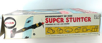

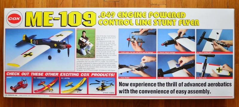
Here's the ME-109 box-art. There looks to be some slight differences between the two models. It was a big model for a Cox ARF... and had a more powerful product-engine.
 Re: Roddie's combat model for reed power.
fly the damn thing already..  not yet... but soon.
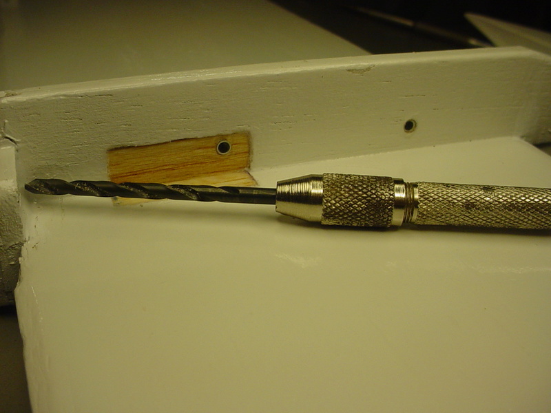
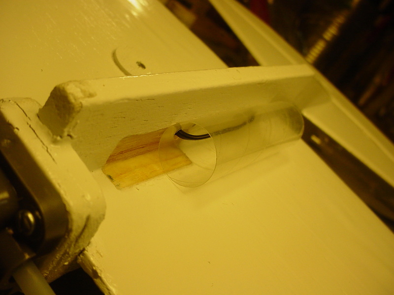
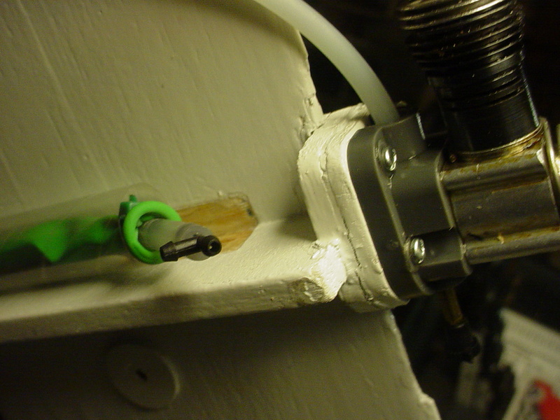
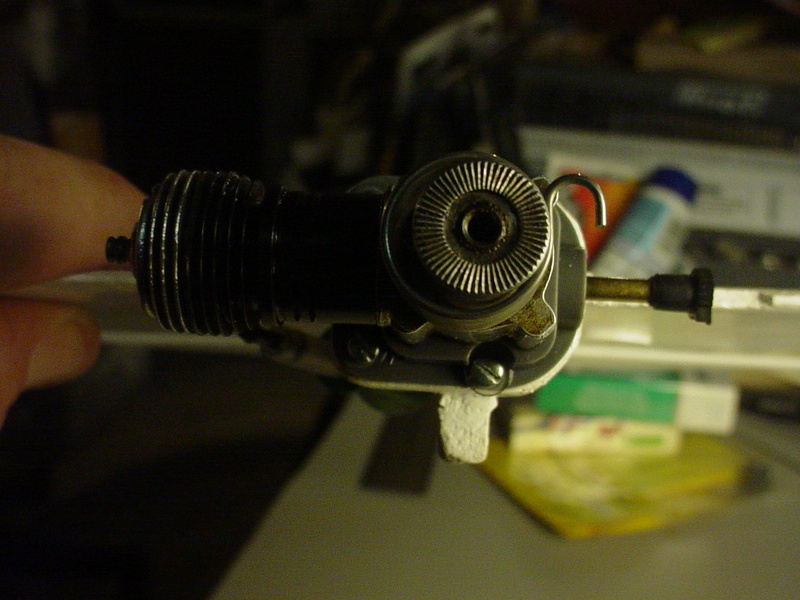
My balloon-capsule mount. I've since primed the new balsa pieces where the hard-tank cut-out was. I needed to fill that area for the forward capsule-mount. I wanted it to be removable so I went ahead with a twisty-tie mount through two aluminum tube-sleeves through the fuse. It's tucked-up under the outboard wing for a really low-profile with the long-thin type balloon installed.
I'm not sure what I'm going to do about a pushrod yet.. The lead-outs will still be solid-wire.. but 1/2 the diameter.. (.015") because of my adjustable-guide layout. I want to keep that. I may go with a CF pushrod. It will save weight in a critical area on this model. The pushrod-hole in the Sig plastic bell-crank isn't much smaller (.052") than the original metal unit.. and I don't like the design of the Sig elevator horn that came with the bell-crank. I want to keep the Dubro horn that has .062" holes. I'll figure it out..


My balloon-capsule mount. I've since primed the new balsa pieces where the hard-tank cut-out was. I needed to fill that area for the forward capsule-mount. I wanted it to be removable so I went ahead with a twisty-tie mount through two aluminum tube-sleeves through the fuse. It's tucked-up under the outboard wing for a really low-profile with the long-thin type balloon installed.
I'm not sure what I'm going to do about a pushrod yet..
 The lead-outs will still be solid-wire.. but 1/2 the diameter.. (.015") because of my adjustable-guide layout. I want to keep that. I may go with a CF pushrod. It will save weight in a critical area on this model. The pushrod-hole in the Sig plastic bell-crank isn't much smaller (.052") than the original metal unit.. and I don't like the design of the Sig elevator horn that came with the bell-crank. I want to keep the Dubro horn that has .062" holes. I'll figure it out..
  Re: Roddie's combat model for reed power.
Did a little more work on this airplane today. I made-up and installed lighter-weight .015" solid-wire lead-outs with a much lighter-weight Sig Nylon 1/2A bellcrank. I provided a slight "rake" to the lead-outs via my adjustable guide. I kept the same pushrod.. and now that the prop is mounted, the balance is in the ballpark. I need a little bit of outboard tip-weight.. but not as much as before. I'm also running the 6 x 2 L/H prop which will roll the model outward-circle.
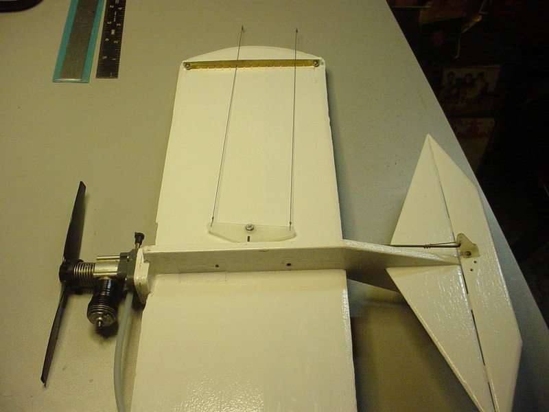
She's under 5oz. dry..
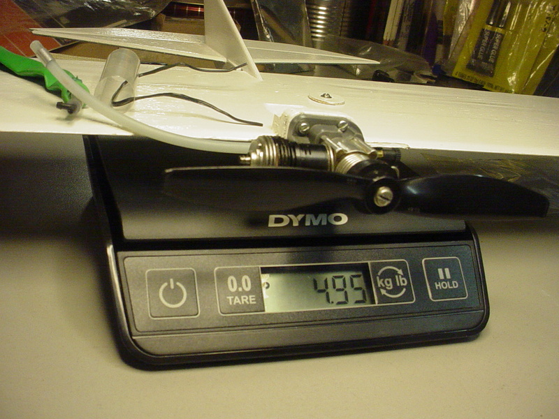

She's under 5oz. dry..

 Re: Roddie's combat model for reed power.
Not sure if she'll balance with the fuel-cell in place "wet".. but I still have the option of mounting that heavy-hub (Cox Super-Stunter spinner-nut)... Not much more I can do at this point if it's tail-heavy, other than affixing a firewall extension. That's actually an easy-fix when running a radial-mounted engine.
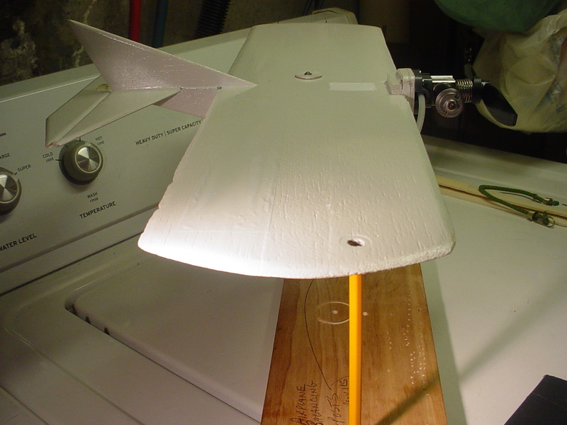
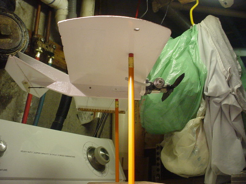
I'm thinking that a "card-table" (I have a few of them..) would be portable enough to transport and use as a platform for a "wing-stooge".. and provide space for gear and also a work-surface. A couple of hook & loop strips could anchor a block or box to the tabletop to increase the stooge-height to around 4 feet. That will hopefully be high enough to gain control when the model is released.
Maybe it's a "curse".. but I like to "think things through" beforehand.. and share these thoughts. They might help someone else to consider their set-up.. and maybe try something different. Nothing ventured.. nothing gained.
 Re: Roddie's combat model for reed power.
Your over thinking. Fly it. Your fuel load is on the cg which makes it a non issue. If your that concerned, put some modeling clay on the nose for the first flight. If you fly with a narrow handle spacing 2" and under, a tail heavy plane is also a non issue.

Ken Cook- Top Poster

- Posts : 5644
Join date : 2012-03-27
Location : pennsylvania
 Re: Roddie's combat model for reed power.
Ken Cook wrote: Your over thinking. Fly it. Your fuel load is on the cg which makes it a non issue. If your that concerned, put some modeling clay on the nose for the first flight. If you fly with a narrow handle spacing 2" and under, a tail heavy plane is also a non issue.
Yes Ken.. You're right. I value your experience.. especially with combat-style models. The narrow handle/line spacing having a positive-influence on a tail-heavy model is something that I did not know. Being of my own design; it's anybody's guess as to how this model will fly. The lead-outs are raked-back slightly through an adjustable "comb-strip" on the inboard wing-tip. It's a feature on my twin P-51 models too. It's a fairly light-weight assembly. I realize that an adjustable-guide is something that only needs to be dialed-in "once".. but I felt it was a good trimming-tool to have on non-proven designs.
Ken, You and Ron Cribbs have been my mentors when it comes to "getting my feet wet again" with flying C/L.. I'll admit.. I'm a bit nervous to try to fly again after so many years. I'm sure that my first trip to the field with two or three ARF's will quench that nervousness.. and turn it into the excitement that I once had. My single flight-attempt almost three years ago with my CEF Reed-Speed Contest model was a real disappointment. I should have had a back-up airplane to fly that day.. just for fun.. but I didn't. My expectations were high and they fell way-short after months of work, following a reprieve of the contest flight-deadline on the last day. Boo Hoo.. blah blah..
For once since I joined CEF 3+ years ago.. I have several airplanes that are ready to fly with rebuilt engines that I've bench-tested and all run good. "This model" won't be the first to fly this season.. but I'm determined to try it after I get back in the groove.
 Similar topics
» Simple .049 Combat Model Plan
» "Boomer" model for Thermal Hopper power
» Reed Speed--Best Model Poll
» Testing model engine power output question
» Roddie's Tee Dee .09
» "Boomer" model for Thermal Hopper power
» Reed Speed--Best Model Poll
» Testing model engine power output question
» Roddie's Tee Dee .09
Page 1 of 1
Permissions in this forum:
You cannot reply to topics in this forum

 Rules
Rules

