Log in
Search
Latest topics
» Duende V model from RC Model magazine 1983.by TD ABUSER Today at 7:20 pm
» Roger Harris revisited
by rsv1cox Today at 10:46 am
» A Little 400 Mile Hop for Some Memory Lane Stuff, and to Hit a Swap Meet.
by getback Today at 7:48 am
» Free Flight Radio Assist
by getback Today at 6:39 am
» Happy 77th birthday Andrew!
by Kim Yesterday at 9:18 am
» Promote the forum with flyers!
by Admin Yesterday at 1:35 am
» Engine choice
by GallopingGhostler Mon Nov 25, 2024 4:03 pm
» My N-1R build log
by roddie Mon Nov 25, 2024 9:19 am
» Night flying at Walters RC park
by 1975 control line guy Sun Nov 24, 2024 7:29 pm
» Cox films/videos...
by GallopingGhostler Sun Nov 24, 2024 7:07 pm
» Cox 020 PeeWee rebuild questions
by LooseSpinner99 Sun Nov 24, 2024 6:13 pm
» Did you spot the Cox engine in this NASA research video?
by balogh Sun Nov 24, 2024 5:08 pm
Cox Engine of The Month
"Rodd-O-Gyro"
Page 2 of 3
Page 2 of 3 •  1, 2, 3
 Re: "Rodd-O-Gyro"
It's starting to look like something Roddie!
Keep it up.
Keep it up.

Cribbs74- Moderator


Posts : 11907
Join date : 2011-10-24
Age : 50
Location : Tuttle, OK
 Re: "Rodd-O-Gyro"
Cut a cardboard circle that is larger than the elevator to use as a pad and sanding guide.
Phil
Phil

pkrankow- Top Poster

- Posts : 3025
Join date : 2012-10-02
Location : Ohio
 Re: "Rodd-O-Gyro"
pkrankow wrote:Cut a cardboard circle that is larger than the elevator to use as a pad and sanding guide.
Phil
I did feather-out the trailing-edge of the elev. some.. but it was still too thick for my liking. I had pre-marked the centerline using the same method as when I cut my hinge-slots. I tried block-sanding at an angle with the block bearing on a scrap piece of hardwood.. but this was laborious and tedious.

The photos below however; show an experiment that I was very happy with! It's a "Smith's" knife sharpener which I used the "fine" (round ceramic rods) side of.
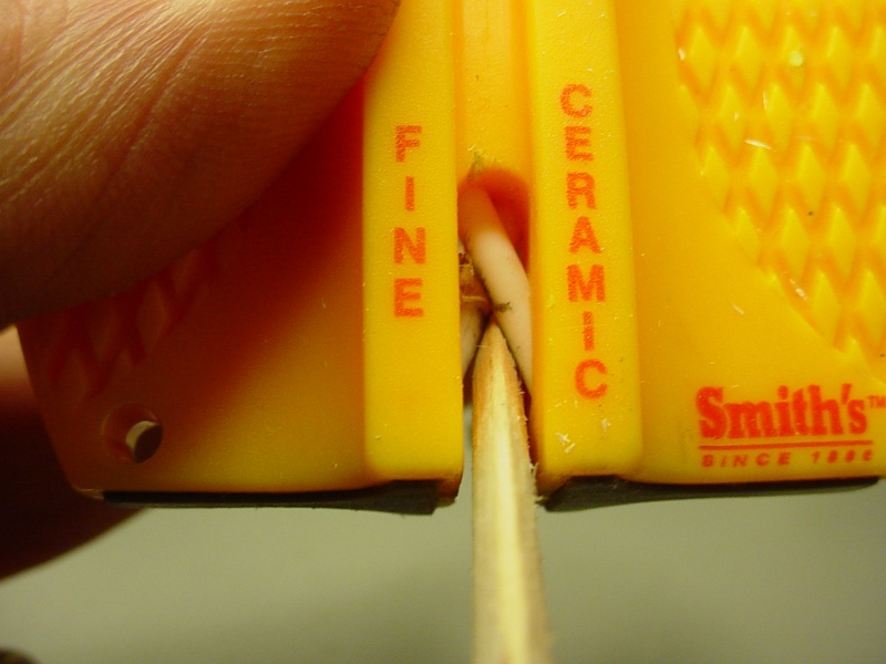
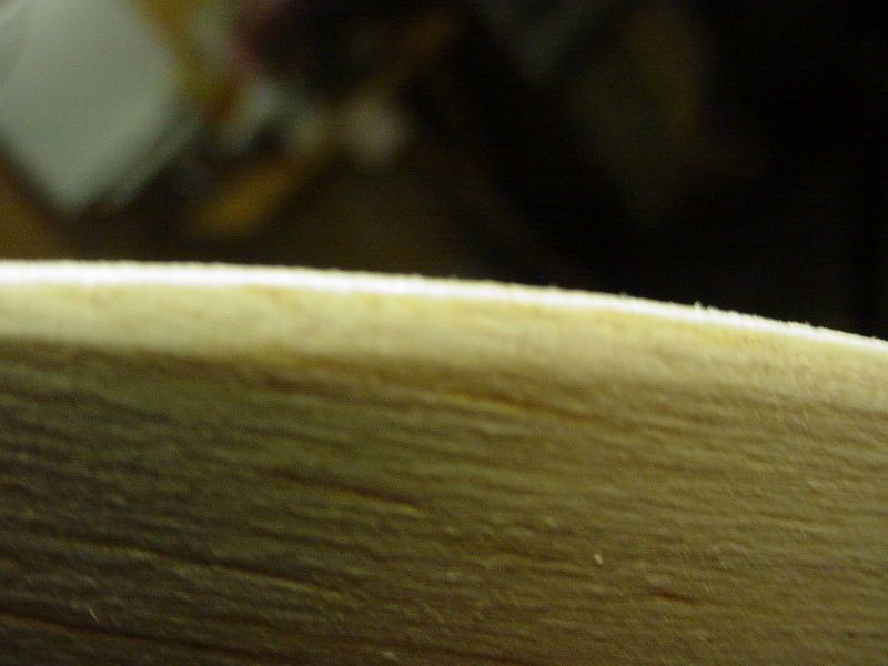
This was quick and easy. Sighting down my curved T/E until the gap closed between the ceramic rods, provided a consistent/even taper. Try it.. you'll like it!
 Re: "Rodd-O-Gyro"
Planing the wood takes seconds and it also prevents the heat generated from sanding from warping the piece. I use my bench planes, but a razor plane that uses single edge razor blades works equally well. Ken

Ken Cook- Top Poster

- Posts : 5644
Join date : 2012-03-27
Location : pennsylvania
 Re: "Rodd-O-Gyro"
Cribbs74 wrote:It's starting to look like something Roddie!
Keep it up.
Thanks Ron,
 Re: "Rodd-O-Gyro"
good little trick on cutting the hinge slots.Im going to start doing mine that way.Thanks for the tip Roddie.

akjgardner- Diamond Member


Posts : 1603
Join date : 2014-12-28
Age : 65
Location : Greensberg Indiana
 Re: "Rodd-O-Gyro"
That Looks pretty darn good Roddie , I have a hinge slot cutter and tried to use it on 1/8 " balsa and had no good sucksess with it , poked through the skin . A thin razor blade may would have done it but probably would slice my finger // if you could cut the razor blade to fit the hinge ? Or not those things are very brittleroddie wrote:CA'd my hinges in and attached the rudders..

getback- Top Poster


Posts : 10448
Join date : 2013-01-18
Age : 67
Location : julian , NC
 Re: "Rodd-O-Gyro"
http://www3.towerhobbies.com/cgi-bin/wti0001p?&I=LXE229
I have this kit. Go to harbor freight and get a $3 set of hobby knives and put the fork in the chisel handle, and the pick in the straight handle.
http://www.harborfreight.com/13-piece-precision-knife-set-32099.html
or get a better set that uses the larger blades.
If you rounded the edge and cannot get the centering tool on the wood use a layer of two of tape on each side.
Sight the tool and the wood to make sure they are in perfect alignment, and work the fork into the wood slowly. Soft balsa can go in one, hard balsa will need a couple takes. Use the pick to clean the slot. In hard balsa use a #11 or similar blade to loosen the wood between the fork marks.
The HF kit is not good for hard digging, so have a quality hobby knife ready to go.
Expect to take at least a minute per pocket, maybe even 5 minutes per pocket in harder balsa. In more robust material like bass or pine you need a saw or to scrape with the back of a knife point.
Yes, I have bloodied my fingers making hinge pockets.
I don't like CA hinges, pin hinges are much more free.
I usually paint before hinging, but cutting pockets before painting allows the support pins for painting to hide inside the pockets so the finish on the edge is perfect.
Locating the hinges and pinning where the slots will go is the next best idea.
For paint take a 1/4 to 1/2 inch stick of whatever, and drill several 1/16 holes along the length all the way through. Put the pins in "crooked" or use bent pins so the surface remains stable and supported. I jokingly call this my "battle axe"

Phil
I have this kit. Go to harbor freight and get a $3 set of hobby knives and put the fork in the chisel handle, and the pick in the straight handle.
http://www.harborfreight.com/13-piece-precision-knife-set-32099.html
or get a better set that uses the larger blades.
If you rounded the edge and cannot get the centering tool on the wood use a layer of two of tape on each side.
Sight the tool and the wood to make sure they are in perfect alignment, and work the fork into the wood slowly. Soft balsa can go in one, hard balsa will need a couple takes. Use the pick to clean the slot. In hard balsa use a #11 or similar blade to loosen the wood between the fork marks.
The HF kit is not good for hard digging, so have a quality hobby knife ready to go.
Expect to take at least a minute per pocket, maybe even 5 minutes per pocket in harder balsa. In more robust material like bass or pine you need a saw or to scrape with the back of a knife point.
Yes, I have bloodied my fingers making hinge pockets.
I don't like CA hinges, pin hinges are much more free.
I usually paint before hinging, but cutting pockets before painting allows the support pins for painting to hide inside the pockets so the finish on the edge is perfect.
Locating the hinges and pinning where the slots will go is the next best idea.
For paint take a 1/4 to 1/2 inch stick of whatever, and drill several 1/16 holes along the length all the way through. Put the pins in "crooked" or use bent pins so the surface remains stable and supported. I jokingly call this my "battle axe"

Phil

pkrankow- Top Poster

- Posts : 3025
Join date : 2012-10-02
Location : Ohio
 Re: "Rodd-O-Gyro"
I have the Dubro kit too.. and yes; pinned hinges are nice. I've done quite a few models using them.

I do like the CA hinges' ease of installation though. I use the Sig "Easy Hinges" and cut them down to 1/4" wide for my 1/2A models. Having a centering guide that's the correct thickness is key. I tend to measure things using a caliper.. so I checked my 1/8" balsa sheet which was .125" (right on the $$) and found a piece of aluminum that measured .060" thick which was close enough to half the wood thickness for me. The width (or depth..) of this aluminum piece is 5/8".. which gives a good flat for the blade to bear on.. so that it cuts straight-in to the wood.
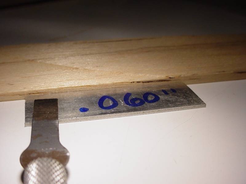
A large-size craft stick (similar to a tongue-depressor) averages 1/16" thickness and it's "width" is slightly over 5/8". This is optimal for pressing a #17 x-acto "chisel" blade flat against it with an index finger, while at the edge of a table-top. The blade will cut a depth of almost 1/2" before the knife-handle hits the table's edge.. (more than deep enough for a hinge) Your other hand holds the stock down tightly against the table-top. A side-rocking motion with slight inward pressure on the handle/blade while keeping it flat.. will accurately cut a hinge slot. Be sure to keep the bevel-side "up" on the blade so that it's sharpened edge is on center with the work-piece's edge. There's no need to have your fingers anywhere near the path of the blade.. or the need to force it to do the job. Just keep both; the blade and the work-piece flat.. and you'll achieve good results. Marking the blade for depth-of-cut isn't a bad idea either.
This #17 blade works great in a single cut, for a 1/4" wide CA hinge.


I do like the CA hinges' ease of installation though. I use the Sig "Easy Hinges" and cut them down to 1/4" wide for my 1/2A models. Having a centering guide that's the correct thickness is key. I tend to measure things using a caliper.. so I checked my 1/8" balsa sheet which was .125" (right on the $$) and found a piece of aluminum that measured .060" thick which was close enough to half the wood thickness for me. The width (or depth..) of this aluminum piece is 5/8".. which gives a good flat for the blade to bear on.. so that it cuts straight-in to the wood.

A large-size craft stick (similar to a tongue-depressor) averages 1/16" thickness and it's "width" is slightly over 5/8". This is optimal for pressing a #17 x-acto "chisel" blade flat against it with an index finger, while at the edge of a table-top. The blade will cut a depth of almost 1/2" before the knife-handle hits the table's edge.. (more than deep enough for a hinge) Your other hand holds the stock down tightly against the table-top. A side-rocking motion with slight inward pressure on the handle/blade while keeping it flat.. will accurately cut a hinge slot. Be sure to keep the bevel-side "up" on the blade so that it's sharpened edge is on center with the work-piece's edge. There's no need to have your fingers anywhere near the path of the blade.. or the need to force it to do the job. Just keep both; the blade and the work-piece flat.. and you'll achieve good results. Marking the blade for depth-of-cut isn't a bad idea either.
This #17 blade works great in a single cut, for a 1/4" wide CA hinge.


 Re: "Rodd-O-Gyro"
Thanks Roddie, that is a very clear and well thought out process.
Phil
Phil

pkrankow- Top Poster

- Posts : 3025
Join date : 2012-10-02
Location : Ohio
 Re: "Rodd-O-Gyro"
pkrankow wrote:Thanks Roddie, that is a very clear and well thought out process.
Phil
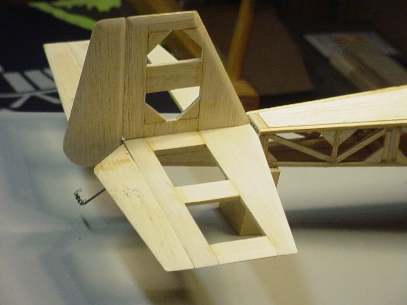
Phil, there's nothing quite like the satisfaction felt, when any style hinges turn-out nice..
I have a self-designed RC trainer with 3 separate hatches.. and I did them all with CA hinges using the above technique.
Top nose-hatch (throttle servo/fuel tank access)

Bottom radio-hatch (receiver/battery access)
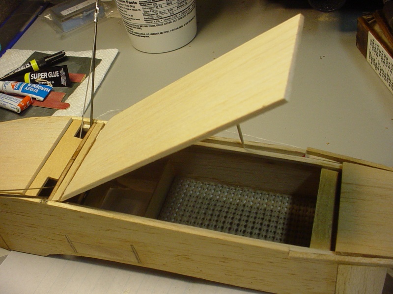
Top rear-hatch (servo/pushrod access)
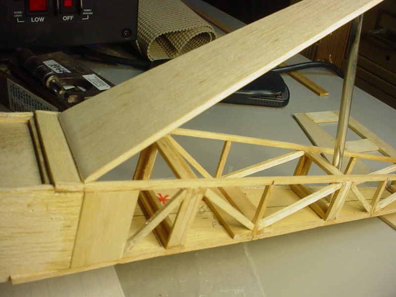
and the tail-feather hinging
 Re: "Rodd-O-Gyro"
Hmm....
Ideas I have not seen before....
hmm....
Nope! I am finishing up a build, triplets, but not quite identical. Not going to contemplate...just going to file away.
Dangum it. Now I have to go look at my incomplete glider rebuild project.
Phil
Ideas I have not seen before....
hmm....
Nope! I am finishing up a build, triplets, but not quite identical. Not going to contemplate...just going to file away.
Dangum it. Now I have to go look at my incomplete glider rebuild project.
Phil

pkrankow- Top Poster

- Posts : 3025
Join date : 2012-10-02
Location : Ohio
 Re: "Rodd-O-Gyro"
That might solve all my magnetic hasp concerns. Better than a hook on the other end, cannot part company with the craft.
Now to solve the balance problem, which probably involves adding a few inches to the fuselage in the nose.
and getting it aloft...cox, electric, EDF? All of the above in turns?
Phil
Now to solve the balance problem, which probably involves adding a few inches to the fuselage in the nose.
and getting it aloft...cox, electric, EDF? All of the above in turns?
Phil

pkrankow- Top Poster

- Posts : 3025
Join date : 2012-10-02
Location : Ohio
 Re: "Rodd-O-Gyro"
pkrankow wrote:Hmm....
Ideas I have not seen before....
hmm....
Nope! I am finishing up a build, triplets, but not quite identical. Not going to contemplate...just going to file away.
Dangum it. Now I have to go look at my incomplete glider rebuild project.
Phil
Oh oh...
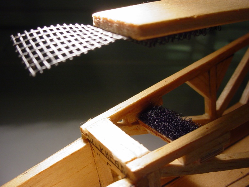
This model was intended for a throttled reedie.. but there's too many places (hatches..
 Re: "Rodd-O-Gyro"
My only hatch is going to be in front of the wing, with the motor on a pylon on the wing, whatever power plant I choose. I'm over 2 years into this rebuild and not getting anywhere fast.
However I am almost done with my pair of flite streaks and a rebuild on an ARF streak!
http://stunthanger.com/smf/index.php/topic,37207.0.html
Phil
However I am almost done with my pair of flite streaks and a rebuild on an ARF streak!
http://stunthanger.com/smf/index.php/topic,37207.0.html
Phil

pkrankow- Top Poster

- Posts : 3025
Join date : 2012-10-02
Location : Ohio
 Re: "Rodd-O-Gyro"
That's a lot of hatches but... nicely done ! I will have to tune my skills I guess , wish I had not glued those cloth hinges on now  Thanks guys

getback- Top Poster


Posts : 10448
Join date : 2013-01-18
Age : 67
Location : julian , NC
 Re: "Rodd-O-Gyro"
getback wrote:That's a lot of hatches but... nicely done ! I will have to tune my skills I guess , wish I had not glued those cloth hinges on nowThanks guys
Eric.. It's all about having fun.. no matter how it's done! There's an old saying; "paint and chrome.. don't get ya' home.." You won't see those cloth hinges when you're tearing up the sky!
 Re: "Rodd-O-Gyro"
Goog job, Roddie. Strange looking,.. but a good start. Is there a reason for the rotors being upside down? Where is your CG at this point? According to what I have read, it should be at the rotor shaft, but in some of R. Harris' videos of his RC autogyros on Utube, the CG is behind the rotor shaft.
Curious for the first rotor test!!
Lieven
Curious for the first rotor test!!
Lieven

OVERLORD- Diamond Member

- Posts : 1807
Join date : 2013-03-19
Age : 58
Location : Normandy, France
 Re: "Rodd-O-Gyro"
OVERLORD wrote:Goog job, Roddie. Strange looking,.. but a good start. Where is your CG at this point? According to what I have read, it should be at the rotor shaft, but in some of R. Harris' videos of his RC autogyros on Utube, the CG is behind the rotor shaft.
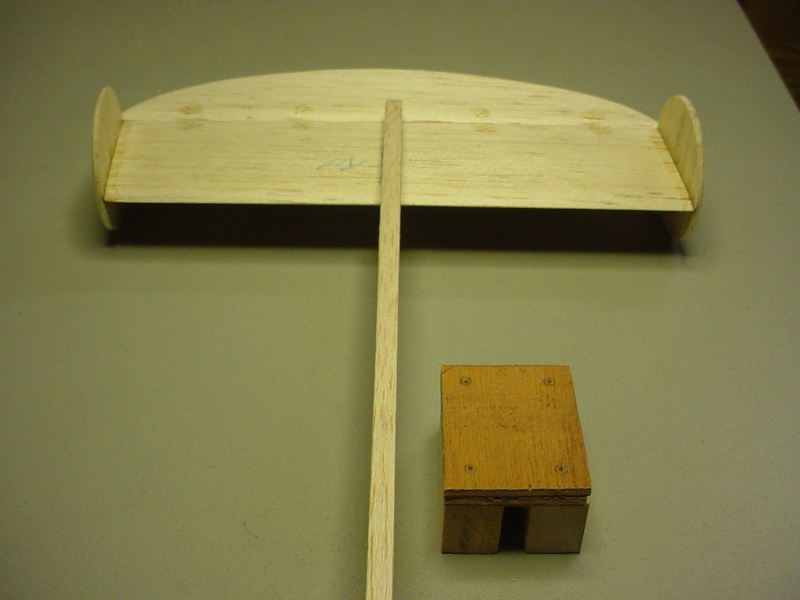
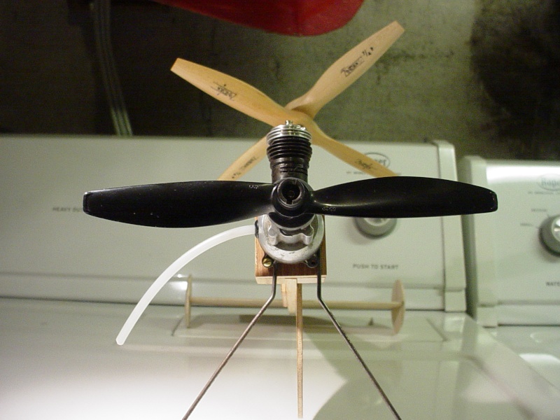
Good questions Lieven.. and thanks for the compliment! As far as the CG is concerned.. I've attempted to make it variable for trimming purposes. I'm expecting that the pair of rotors shown, may not work out. If I need larger diameter rotors; I wanted to be able to compensate for their weight. The "pod" that the rotor-shaft is mounted to, can be repositioned fore/aft in the fuse.

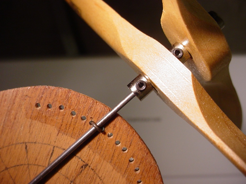
The angle of attack is also variable. The photos below show the "pod" being rotated to vary the AOT.. but there is a major hurdle with fitting a bellcrank mount.. which would need to stay parallel with the fuse. The rotor-shaft mount design allows varying the AOT as well.. and the pod; need not be rotated if it's going to be a problem.
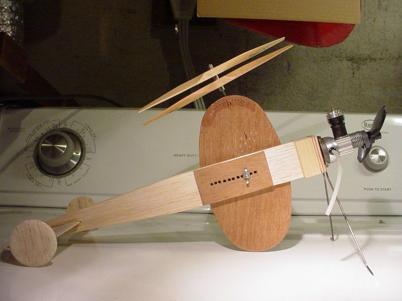
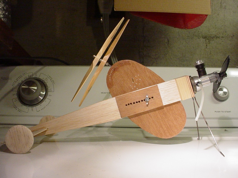
The above photos show the pod being rotated to the extremes.. but it is NOT planned to be adjustable in flight. I had wondered about having the rotors tilt fore/aft to vary pitching the model up/down (on the same idea as differential-flaps linked to the elevator).. but that's going even further out on a limb.... that I'm already too far out on!
Then there's still the issue of fitting lead-outs and some sort of inboard stub-wing to support them. This would also require the pod to stay stationary.

OVERLORD wrote:Is there a reason for the rotors being upside down?
Curious for the first rotor test!!
Lieven
The rotor-blades..
 Here is where I'm unsure when using conventional propellers; whether to mount them facing into the airstream.. or away from it. My thinking is; to orient them where they will be "more" resistant to turning. This may seem to be a strange approach.. but I want them to "catch" the wind at a given AOT to provide lift. I don't know whether facing toward or away will create the most resistance in a freewheeling configuration... or whether the contra-rotating props will even work. I've tried to design this thing to easily try an infinite number of configurations. It only needs to become airborne.. and I'll consider it a success.
I'll probably end-up with a tether-car!!

 Re: "Rodd-O-Gyro"
Well at first I thought it was done ? Were the wing //// Looks like you will need to move the rotor adjustment to the other side and MAYBE put a 1/2 wing on with struts to help support ?? I would think for lift the rotors at least the bottom one will need to bee on like a RH one would mount ( if you put a prop on a wire and hit , spin it the right way it will lift off , but not if upside down ) Just saying Yeah that's different 


getback- Top Poster


Posts : 10448
Join date : 2013-01-18
Age : 67
Location : julian , NC
 Re: "Rodd-O-Gyro"
Roddie, to solve the bellcrank problem, couldn't you fix your oval on the starboard side of the fuse? - I think that's what Eric meant - then you can fix the stub wing and bellcrank permanently to the fuse.

OVERLORD- Diamond Member

- Posts : 1807
Join date : 2013-03-19
Age : 58
Location : Normandy, France
 Re: "Rodd-O-Gyro"
OVERLORD wrote:Roddie, to solve the bellcrank problem, couldn't you fix your oval on the starboard side of the fuse? - I think that's what Eric meant - then you can fix the stub wing and bellcrank permanently to the fuse.
Yes, that would simplify things. I'm scratching my head now.. wondering why I didn't put the oval on the outboard side to start with. I had initially thought about mounting an inboard (only) stub-wing to the oval.. which would deflect when the oval was rotated (if needed..) to help with lift. IE: if the top of the oval were rotated rearward.. it would increase the stub-wings' angle of attack. This is a classic example of my over-thinking things.. and making it more complicated than it needs to be.
One the objectives to this build.. is to see if I can make it fly by using the rotors alone.. without stub-wings. I think it's possible.. but I could be wrong. This is where I need to figure out which is the best way to face the rotor/props. As Eric mentioned.. whacking a prop in the direction of it's pitch, will cause it to rise.. but this would simulate it being powered.. which it is not. It will be catching the wind from the prop-blast and forward movement. I mentioned mocking-up a "whip-model".. which wouldn't be difficult, and may provide the answers.
 en"dear"ing..
My wife (God bless her soul..) comes down into my workshop and notices the Rodd-O-Gyro for the first time.. "What's this"? she asks.. "Oh.. just something I've been working on" I reply.. She picks it up.. and exclaims.. "it's heavy"... 


 (thanks for the words of encouragement hon..)
Page 2 of 3 •  1, 2, 3
 Similar topics
» Cox Auto-Gyro
» Auto- Gyro projects?
» The Cars are the Stars Contest.
» "Against all Odds" Rodd-E-Liminator vids
» Cars-Stars 2019 "Rodd-E-Liminator"
» Auto- Gyro projects?
» The Cars are the Stars Contest.
» "Against all Odds" Rodd-E-Liminator vids
» Cars-Stars 2019 "Rodd-E-Liminator"
Page 2 of 3
Permissions in this forum:
You cannot reply to topics in this forum

 Rules
Rules

