Log in
Search
Latest topics
» Tee Dee .020 combat modelby Ken Cook Today at 3:23 am
» My latest doodle...
by batjac Yesterday at 9:47 pm
» My N-1R build log
by roddie Yesterday at 8:50 pm
» Free Flight Radio Assist
by rdw777 Yesterday at 4:51 pm
» Purchased the last of any bult engines from Ken Enya
by getback Yesterday at 12:05 pm
» Funny what you find when you go looking
by rsv1cox Wed Nov 20, 2024 3:21 pm
» Landing-gear tips
by 1975 control line guy Wed Nov 20, 2024 8:17 am
» Cox NaBOO - Just in time for Halloween
by rsv1cox Tue Nov 19, 2024 6:35 pm
» Canada Post strike - We are still shipping :)
by Cox International Tue Nov 19, 2024 12:01 pm
» Duende V model from RC Model magazine 1983.
by getback Tue Nov 19, 2024 6:08 am
» My current avatar photo
by roddie Mon Nov 18, 2024 9:05 pm
» Brushless motors?
by rsv1cox Sun Nov 17, 2024 6:40 pm
Cox Engine of The Month
"Honker" build thread
Page 1 of 2
Page 1 of 2 • 1, 2 
 "Honker" build thread
Well, having had to shelve indefinitely any large building projects (like my "Coy Lady") due to my workshop being filled with "Temporarily" stored furniture and grandchildren's playhouse, I have had to find something smaller to build.
I've decided on the "Honker" which Andrew posted the plans for a while back, to be powered by a throttled SureStart, and have rudder/throttle/elevator controls.

Wing glued up

Aerofoil shaping started, unfortunately, since Sig tapered balsa is not available over here, I am having to do it the hard way! I have a few reservations about being able to produce an even taper to the 1/4" sheet, but using a suitable template to check as I go I'm hoping for reasonable accuracy, since I think a variable aerofoil section could produce some interesting flight characteristics!
More to come!
I've decided on the "Honker" which Andrew posted the plans for a while back, to be powered by a throttled SureStart, and have rudder/throttle/elevator controls.

Wing glued up

Aerofoil shaping started, unfortunately, since Sig tapered balsa is not available over here, I am having to do it the hard way! I have a few reservations about being able to produce an even taper to the 1/4" sheet, but using a suitable template to check as I go I'm hoping for reasonable accuracy, since I think a variable aerofoil section could produce some interesting flight characteristics!
More to come!

Ivanhoe- Diamond Member

- Posts : 1752
Join date : 2011-09-30
Location : Northern Ireland
 Re: "Honker" build thread
Wilf:
I find a sanding bar very helpful when shaping airfoils. I use the ones from Great Planes. They're aluminum and come in a variety of lengths to suit the application. The sandpaper for them adheres to the aluminum and comes in a variety of grits.
I find a sanding bar very helpful when shaping airfoils. I use the ones from Great Planes. They're aluminum and come in a variety of lengths to suit the application. The sandpaper for them adheres to the aluminum and comes in a variety of grits.

SuperDave- Rest In Peace

- Posts : 3552
Join date : 2011-08-13
Location : Washington (state)
 Re: "Honker" build thread
Yo Wilf!
A small hand-planer with a new blade will make the job go a lot quicker !
A small hand-planer with a new blade will make the job go a lot quicker !

Kim- Top Poster


Posts : 8625
Join date : 2011-09-06
Location : South East Missouri
 Re: "Honker" build thread
Wilf here is how I do it.
Get a thin sheet of aluminium and cut out the airfoil shape then use that outcut bit as a template to see if the airfloil is correct.
Another idea I have had but not tried is to get a thicker piece of aluminium and do the same but cut this piece in half.
From LE to TE straight then stick some sticky sand paper to both sides and then use that to sand in the airfoil after we have a basic shape.
It seems like it would work.
Maybe next time I have a sheet wing project I will try it.
 Re: "Honker" build thread
While Kim's suggestion has merit for roughing out" an airfoil a bar sander is better for the finish work. I have an 11" bar sander which has been perfect for most of my applications on smaller planes. The 5.5" bar sander also works well.
Wilf: As shown in your picture your sander is too small to do a consistant airfoil profile IMO.
Wilf: As shown in your picture your sander is too small to do a consistant airfoil profile IMO.

SuperDave- Rest In Peace

- Posts : 3552
Join date : 2011-08-13
Location : Washington (state)
 Re: "Honker" build thread
Kim wrote:Yo Wilf!
A small hand-planer with a new blade will make the job go a lot quicker !

Yes, it does, doesn't it!

Ivanhoe- Diamond Member

- Posts : 1752
Join date : 2011-09-30
Location : Northern Ireland
 Re: "Honker" build thread
nitroairplane wrote:Wilf here is how I do it.
Get a thin sheet of aluminium and cut out the airfoil shape then use that outcut bit as a template to see if the airfloil is correct.
Another idea I have had but not tried is to get a thicker piece of aluminium and do the same but cut this piece in half.
From LE to TE straight then stick some sticky sand paper to both sides and then use that to sand in the airfoil after we have a basic shape.
It seems like it would work.
Maybe next time I have a sheet wing project I will try it.
Luckily, the Honker has a Jedelsky wing, so the rearmost section is a straight taper, not a conventional aerofoil, so I can get away with a simple ply template. So far so good!

Ivanhoe- Diamond Member

- Posts : 1752
Join date : 2011-09-30
Location : Northern Ireland
 Re: "Honker" build thread
nitroairplane wrote:That's lucky!
Any chance of a video of the hopefully succesful maiden?
Unfortunately I don't own a video camera, I really must try to get one some day!

Ivanhoe- Diamond Member

- Posts : 1752
Join date : 2011-09-30
Location : Northern Ireland
 Re: "Honker" build thread
[quote="Ivanhoe"]
Unfortunately I don't own a video camera, I really must try to get one some day
I use my phone and the quality is very good.
Example of it.
nitroairplane wrote:That's lucky!
Any chance of a video of the hopefully succesful maiden?
Unfortunately I don't own a video camera, I really must try to get one some day Re: "Honker" build thread
[quote="nitroairplane"]
Duhh, don't have a smartphone either, just use my prehistoric mobile to make phone calls,
If I could afford a smartphone, I could afford a video camera!
Ivanhoe wrote:nitroairplane wrote:That's lucky!
Any chance of a video of the hopefully succesful maiden?
Unfortunately I don't own a video camera, I really must try to get one some day
Ivanhoe- Diamond Member

- Posts : 1752
Join date : 2011-09-30
Location : Northern Ireland
 Re: "Honker" build thread
Ivanhoe wrote:
Luckily, the Honker has a Jedelsky wing, so the rearmost section is a straight taper, not a conventional aerofoil, so I can get away with a simple ply template. So far so good!
One way to build in a straight taper is to use music wire. For a 1/4" to 1/8" taper, lay a piece of 1/4" music wire against one edge of the sheet and an 1/8" piece against the other edge. Take a 5" flat sanding block and tack on a course grit paper. Sand down to the wires using the block "chord wise". The wire will ensure an even thickness all along both edges and the taper will be uniform all along the sheet.
 Re: "Honker" build thread

Fuselage sides ready for assembly. Now, because the Honker has no formers in the fuselage I'm looking for tips as to the best way to go about assembling it. Anyone who has built this model and would like to tell me the best and easiest way to go about it would be more than welcome to chip in!
I would, ideally, like to be able to install the servos and pushrods while the fuselage is still partially open, but without formers to hold it in shape I am struggling how to do it, I suppose I could always install temporary formers, but if anyone knows a better way please tell me!
Wilf

Ivanhoe- Diamond Member

- Posts : 1752
Join date : 2011-09-30
Location : Northern Ireland
 Re: "Honker" build thread
I'm terribly late with this reply since you've probably already got the wing shaped, but I used the jigs that came with another kit to shape the LE when I built my Li'l Satan. I glued 4 of them together and pressed sandpaper into the curve. It made a perfect Lead edge shape after I got in the neighborhood with a small hand plane.
Here are the jigs I made into a shaping block. Should be easy to make a similar block:
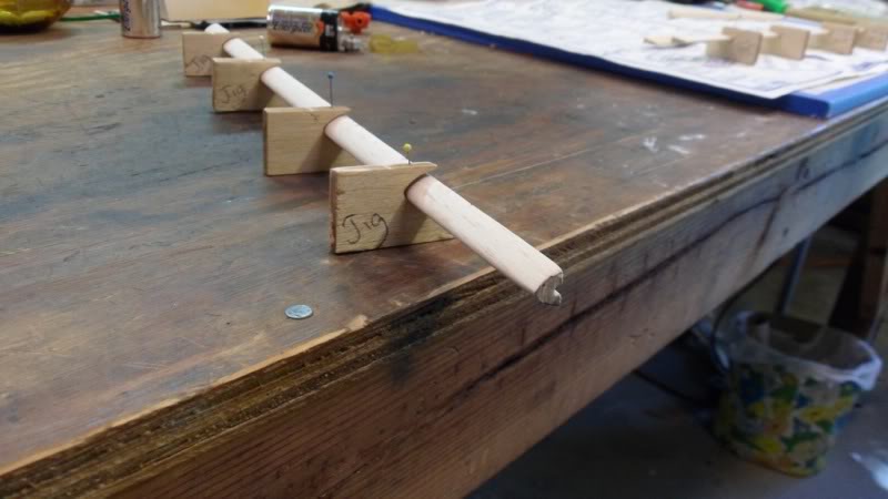
Here are the jigs I made into a shaping block. Should be easy to make a similar block:

_________________
Don't Panic!
...and never Ever think about how good you are at something...
while you're doing it!
My Hot Rock & Blues Playlist
...and never Ever think about how good you are at something...
while you're doing it!
My Hot Rock & Blues Playlist

RknRusty- Rest In Peace

- Posts : 10869
Join date : 2011-08-10
Age : 68
Location : South Carolina, USA
 Re: "Honker" build thread
OK, Wilf ---
This is a little long, but feel free to ignore any or all of my rantings. The fuselage sides forward of the trailing edge doublers are parallel -- this is where we're going to start.
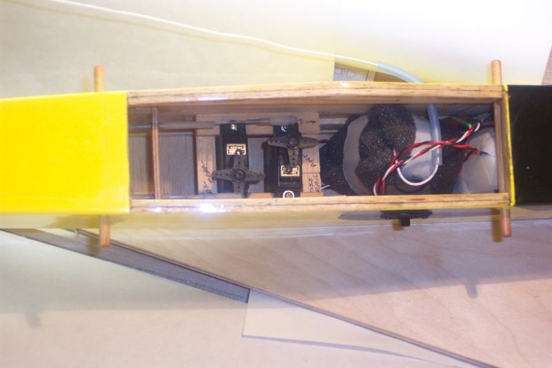
1. Mark and glue in the servo rails, only the parts that attach to the fuselage sides, not the servo tray. Don't use the specified plywood -- these planes were way over-designed in the 70's. I used 1/8" x 1/2" balsa strips and made the strips longer than the tray. This will allow you to slide the tray forward or rearward to adjust the CG if needed. I calculated the position so I would have about 1/8" clearance between the bottom of the servos and the bottom sheeting. I built my tray separately and just dropped it into place later – gluing after estimating CG.
2. Notice that the cross piece that supports the cable sheaths is glued to a block on the fuselage side. Add this 1/8" balsa block at the same time. Leave room to add a crosspiece that supports the top sheeting.
3. Don't forget to build your right fuselage side shorter to ensure right-thrust for your firewall. I would suggest that you add 3/16" square verticals between the top and bottom longerons on the front. End grain joints are characteristically poor due to the small area and potential dry joints as the adhesive wicks into the end grain. These verticals will ensure the fuselage side doesn't bow before the firewall is attached and add significant strength to the design, primarily because of the increased gluing surface. Anytime I attach a firewall, I want all sides to be glued to either additional square or triangular stock. Don't forget that this is the part that usually arrives at the wreck first. I always use epoxy for firewall attachment -- it's fuelproof and less prone to vibration stress fractures than CA.
4. Edge glue two pieces of the 3/32" crossgrain bottom sheeting together and make sure opposing sides are absolutely parallel and perpendicular to the adjacent sides. The length of these pieces should be the exact width of the fuselage -- this piece will determine the alignment of your fuselage. Take a piece of drawing paper or sheets that have been taped together and draw two parallel lines the length of the fuselage and as wide as the fuselage forward of the TE doublers. Tape this to your building board leaving room on both sides. Lay down a sheet of wax paper or food wrap on your alignment sheet that's larger than the bottom sheeting piece. Pin your bottom sheeting to the board leaving room along the edges -- it should fit exactly to the lines you've drawn. Pin a piece of scrap 3/32" to the board to support the end of the fuselage sides. Your fuselage sides will need an alignment mark to use when gluing to the bottom sheeting – I would probably place it about in the center of the TE doubler. It MUST be in the identical location on both sides --- you can’t align the front since one side is offset.
5. Fold the wax paper over the bottom sheeting and set one of your building blocks right up against the edge of the bottom sheeting. This wax paper will keep you from gluing the fuselage to the building block. Take your left fuselage side (or right, depending which side you want to start with), firewall to the left and align your fuselage mark with the edge of the bottom sheeting. The scrap sheeting should be supporting the tail. Use another block to make sure the tail end of the fuselage is even with one of the parallel lines. Holding the fuselage side against your building block – the ones on your board look to be heavy and square – run a bead of CA along the inside bottom of the fuselage until the fuselage begins to curve away from the bottom sheeting. Hold until cured – you should have 4” or 5” glued along the bottom at this time. Now, leaving everything in place, do the same for the other side. You may want to pin the tail down to the support scrap to ensure the fuselage is not canted. This will set the alignment, both fore and aft and side to side, so care here is critical.
6. In the attached picture, there is a crosspiece that supports the top sheeting right at the TE location – you can’t see it. You could add this just for additional support at this time. I would also pin a large piece of scrap to the firewall location to maintain alignment when you add the top deck. Cut your ¼” nose deck – accuracy here is also important – and glue into place. Using scrap on the nose bottom to keep the sides parallel and vertical when adding the deck would also be a good idea. Once the nose deck is in place and cured, unpin, flip over, reblock to the alignment sheet and add the rest of the bottom sheeting forward to the firewall. I usually cut most of my sheeting a little oversize and then sand to fit after installed – it seems to go a little faster without worrying about alignment and size. This plane doesn't need a wheel.
7. Use your parallel lines to fix the location for the end of the fuselage, pull the sides together and finish out the bottom sheeting all the way to the end using your blocks to ensure the sides are vertical. The plans don’t show it, but I added a wing saddle doubler before pulling the tail together – this area can take some licks and a doubler will also keep the top from bowing. I would add it at the same time that you added the servo rails. You can also glue in a couple of pieces of 1/8” x 1/4" strips to the bottom of the top rear longeron to hold the sides vertical until the top sheeting is added. These won’t get in the way while you’re adding your pushrods.
Whew – I know this is long, but it will probably go faster than reading the post.
andrew

 Re: "Honker" build thread
Thanks a lot, Andrew, that is exactly what I need, your system is similar to how I was thinking it would have to go, that and the other tips are invaluable
Thanks for taking the trouble to help me out
Wilf
Thanks for taking the trouble to help me out
Wilf

Ivanhoe- Diamond Member

- Posts : 1752
Join date : 2011-09-30
Location : Northern Ireland
 Re: "Honker" build thread
Wow, so much more than meets the untrained eye.
_________________
Don't Panic!
...and never Ever think about how good you are at something...
while you're doing it!
My Hot Rock & Blues Playlist
...and never Ever think about how good you are at something...
while you're doing it!
My Hot Rock & Blues Playlist

RknRusty- Rest In Peace

- Posts : 10869
Join date : 2011-08-10
Age : 68
Location : South Carolina, USA
 Re: "Honker" build thread
So far, so good...........


Fuselage is going together, next I have to decide on the three servo positions and install them and the pushrods before I finish the top sheeting.


Fuselage is going together, next I have to decide on the three servo positions and install them and the pushrods before I finish the top sheeting.

Ivanhoe- Diamond Member

- Posts : 1752
Join date : 2011-09-30
Location : Northern Ireland
 Re: "Honker" build thread
Well, progress is slow, but I'm getting there!

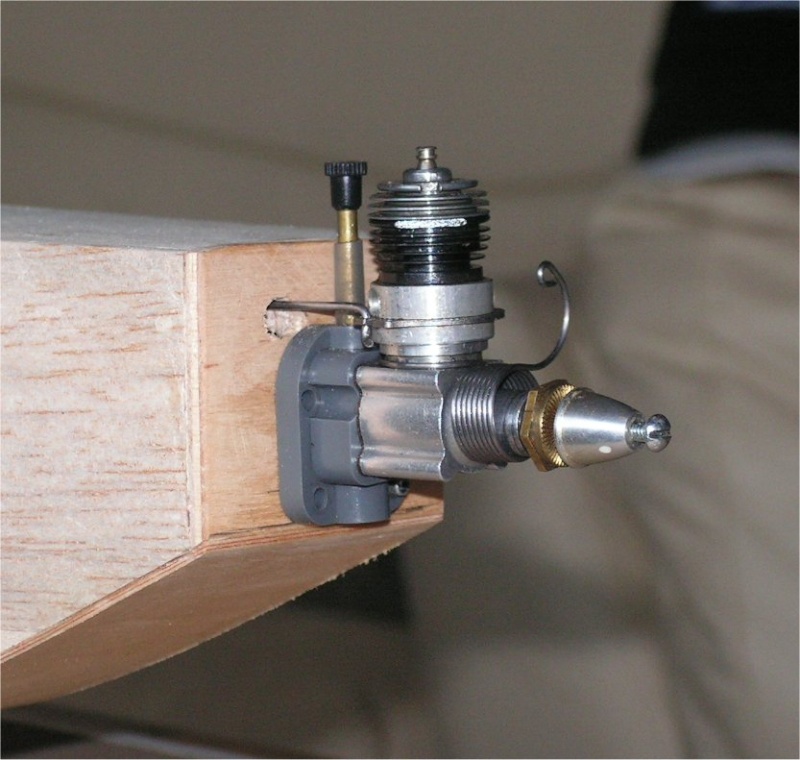
Fitting the throttle pushrod was about the trickiest bit! I had to fit all the nose sheeting before I tried to thread it through, ended up inventing new swearwords before I'd finished!

All the controls are now connected, and actually work properly! (Yes, I could have used all small servos, but I prefer the reliability of full-sized ones when I can)

I shall almost certainly have to alter horns and things to cut down the control surface movements, they are a bit excessive at present.
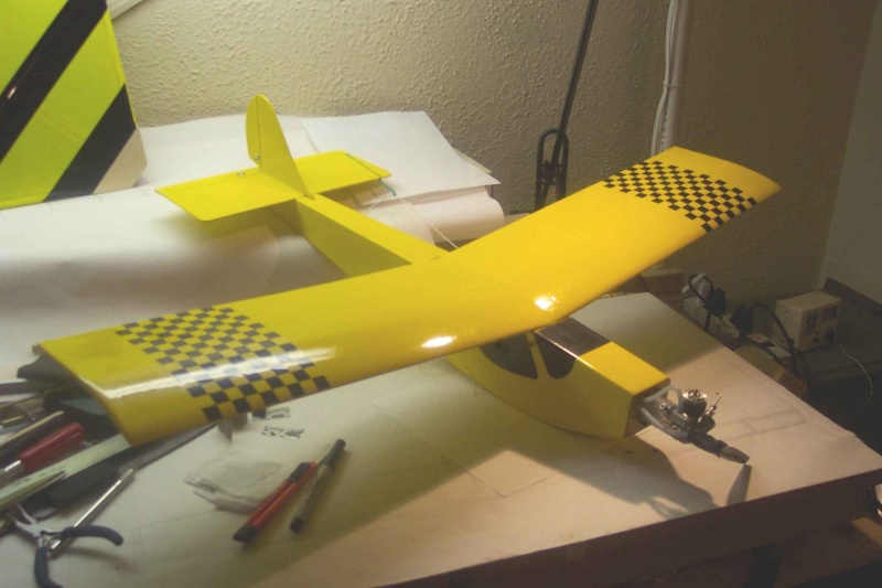
I'm almost ready for final sanding and covering now, I think I may go for all yellow, like Andrew's, I like that look.


Fitting the throttle pushrod was about the trickiest bit! I had to fit all the nose sheeting before I tried to thread it through, ended up inventing new swearwords before I'd finished!

All the controls are now connected, and actually work properly! (Yes, I could have used all small servos, but I prefer the reliability of full-sized ones when I can)

I shall almost certainly have to alter horns and things to cut down the control surface movements, they are a bit excessive at present.
I'm almost ready for final sanding and covering now, I think I may go for all yellow, like Andrew's, I like that look.

Ivanhoe- Diamond Member

- Posts : 1752
Join date : 2011-09-30
Location : Northern Ireland
 Re: "Honker" build thread
Ivanhoe wrote:I shall almost certainly have to alter horns and things to cut down the control surface movements, they are a bit excessive at present.
I'm almost ready for final sanding and covering now, I think I may go for all yellow, like Andrew's, I like that look.
Not to worry about spending time --- you've got a very nice plane going there.
Just move your clevises to the outside holes on the horns for your rudder and elevator. That should tame down your movement somewhat.
[img]
 [/img]
 Re: "Honker" build thread
I think the Honker needs a decal


Ivanhoe- Diamond Member

- Posts : 1752
Join date : 2011-09-30
Location : Northern Ireland
 Re: "Honker" build thread
Well, the structure is completed, covering starting soon I hope


A quick check of the CG shows it's about an inch too far back, I'll wait until the covering's on before I move the battery to get it nearer where it should be.


A quick check of the CG shows it's about an inch too far back, I'll wait until the covering's on before I move the battery to get it nearer where it should be.

Ivanhoe- Diamond Member

- Posts : 1752
Join date : 2011-09-30
Location : Northern Ireland
Page 1 of 2 • 1, 2 
 Similar topics
» Anyone have plans for the Blink?
» SIG Wonder build thread - ASP12 vs COX TD09
» Dragonfly Build Thread
» The RMH Bipe build thread
» Scratch built Sig Staggerwing build thread.. Version 3.0
» SIG Wonder build thread - ASP12 vs COX TD09
» Dragonfly Build Thread
» The RMH Bipe build thread
» Scratch built Sig Staggerwing build thread.. Version 3.0
Page 1 of 2
Permissions in this forum:
You cannot reply to topics in this forum

 Rules
Rules

